
Specifications


14 Rapier Series Switch
C613-03020-00 REV N
LEDs and What They Mean
The following LEDs report operations and faults on Rapier switches:
■ System LEDs on the Rapier 48w and 48w-B
■ System LEDs on all models except Rapier 48w and 48w-B
■ Switch port LEDs on the Rapier G6
■ Switch port LEDs on the Rapier G6F-LX/SC, G6F-SX/SC, and G6F-SX/
MT-RJ
■ Switch port LEDs on the Rapier 8/8SC, 8/8MT, 24, 24i 24i-B, 48, 48i, 48w,
and 48w-B
■ Switch port LEDs on the Rapier 16F-FX/SC, 16Fi-FX/SC, 16F-FX/MT-RJ,
and 16Fi-FX/MT-RJ
■ SFP Port LEDs on the Rapier 48w and 48w-B
Uplink modules, NSMs, and PICs are expansion options and must be
purchased separately. For information about LEDs on uplink modules, NSMs,
and PICs, see:
■ Uplink Module Installation and Safety Guide
■ Uplink Module Hardware Reference
■ Network Service Module Installation and Safety Guide
■ Network Service Module Hardware Reference
■ Port Interface Card Hardware Reference
You can download these documents from
www.alliedtelesis.com/support/software.
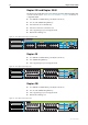
Table 1: System LEDs on the Rapier 48w and 48w-B
LED State Function
Power Green The switch is receiving power and the voltage is
within the acceptable range.
Fault Red The switch or management software is
malfunctioning.
1 flash A switch fan has failed.
In use
(front panel)
Green An NSM is installed, is receiving power, and is
operational. The NSM and its PICs are not ready to
be hot swapped.
Off No NSM is installed, or the switch has not recognised
the NSM.
Swap
(front panel)
Green The NSM and its PICs are ready to be hot swapped.
Off The Hot Swap button must be pressed before the
NSM or PICs can be hot swapped, or the software
version does not support hot swapping
1
.
1. Hot swapping is supported by Software Version 2.3.1 or later. AT-AR021(S) BRI S/T, AT-AR021(U)
BRI U, and AT-AR023 SYN PICs can be hot swapped.