Rapier Series Switch Hardware Reference Rapier 16fi Rapier 24i Rapier 24i-B Rapier 48i Rapier 48w Rapier 48w-B
Rapier Series Switch Hardware Reference Rapier G6 Rapier G6F-LX/SC Rapier G6F-SX/SC Rapier G6F-SX/MT-RJ Rapier 8/8MT Rapier 8/8SC Rapier 16F-FX/MT Rapier 16F-FX/SC Rapier 16Fi-FX/MT Rapier 16Fi-FX/SC Rapier 24 Rapier 24i Rapier 24i-B Rapier 48 Rapier 48i Rapier 48w Rapier 48w-B Download the complete document set from www.alliedtelesis.
Rapier Series Switch Hardware Reference Document Number C613-03020-00 REV N © 2008 Allied Telesis, Inc. All rights reserved. No part of this publication may be reproduced without prior written permission from Allied Telesis, Inc. Allied Telesis, Inc. reserves the right to change specifications and other information in this document without prior written notice. The information provided herein is subject to change without notice. In no event shall Allied Telesis, Inc.
Hardware Reference 3 Contents Models Covered by this Document .................................................................... 4 Hardware Overview .......................................................................................... 5 Rapier Switch Models ................................................................................. 8 Rapier G6 ................................................................................................... 8 Rapier G6F-LX/SC ................................
4 Rapier Series Switch Models Covered by this Document This Hardware Reference contains information on the following devices: ■ Rapier G6 switch ■ Rapier G6F-LX/SC switch ■ Rapier G6F-SX/SC switch ■ Rapier G6F-SX/MT-RJ switch ■ Rapier 8/8MT switch ■ Rapier 8/8SC switch ■ Rapier 16F-FX/MT-RJ switch ■ Rapier 16Fi-FX/MT-RJ switch ■ Rapier 16F-FX/SC switch ■ Rapier 16Fi-FX/SC switch ■ Rapier 24 switch ■ Rapier 24i switch ■ Rapier 24i-B switch ■ Rapier 48 switch ■ Rapier 48i switch
Hardware Reference 5 Hardware Overview This section provides an overview of the hardware features of Rapier Series switches. Rapier switches combine wire-speed Layer 2 and 3 switching with full multiprotocol routing capabilities to deliver low-latency high-bandwidth traffic capabilities to the desktop. Ethernet, fast Ethernet and gigabit Ethernet connectivity with both copper and fibre optic interfaces make the Rapier Series a versatile and powerful switching solution.
6 Rapier Series Switch Regulatory standards All models except DC models of the Rapier 48w and 48w-B ■ EMC: FCC CFR47 Part 15 Class A, EN55022 Class A, VCCI Class A, AS/ NZS CISPR22 Class A, EN61000-3-2/3, EN55024 ■ Safety: UL60950-1, CAN/CSA-C22.2 No. 60950-1-03, 21 CFR 1040, EN60950-1, AS/NZS 60950.1, EN 60825-1 DC models of the Rapier 48w and 48w-B LEDs NEBS Power supply ■ EMC: FCC CFR47 Part 15 Class A ■ Safety: UL60950-1, CAN/CSA-C22.2 No. 60950-1-03, 21 CFR 1040, EN60950-1, AS/NZS 60950.
Hardware Reference 7 Rapier 8/8MT, 8/8SC, 16F-FX/MT, 16F-FX/SC, 24, 48 ■ ASIC switch chip ■ Non-blocking L2 and L3 IP switching Rapier G6, G6F/LX, G6F/SX, G6F/MT Processing core ■ Gigabit ASIC switch chip ■ Non-blocking L2 and L3 IP switching All models except Rapier 48w and 48w-B ■ 200MHz RISC processor (250MHz for Rapier 24i models with revision N or later PCBs) ■ 32MBytes Synchronous DRAM ■ 6MBytes flash memory (16MBytes for Rapier i models) ■ 128KBytes Non-volatile Storage (battery ba
8 Rapier Series Switch Rapier Switch Models This section provides hardware descriptions for individual switch models.
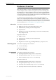
Hardware Reference 9 Rapier G6F-SX/MT-RJ ■ 6 x 1000BASE-SX ports (MT-RJ fibre connectors) ■ Two 10/100/1000BASE uplink bays ■ Layer 3 managed switch Figure 4: Front panel of the Rapier G6F/MT Rapier G6f Layer 3 Gigabit Ethernet Switch 7 RS-232 TERMINAL PORT PORT ACTIVITY 1000BASE-SX / MT-RJ ASYN0 1 2 L/A 3 L/A 4 L/A 5 L/A 6 L/A 8 D/C D/C D/C D/C STATUS FAULT L/A CLASS 1 LASER PRODUCT DO NOT STARE INTO BEAM D/C L/A LINK D/C FULL DUP ACTIVITY RPS HALF DUP COL PWR RES
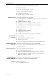
10 Rapier Series Switch Rapier 16F-FX/MT-RJ ■ 16 x 100BASE-FX ports (MT-RJ fibre connectors) ■ Two 1000BASE uplink bays ■ One Network Service Module bay ■ One PCI Accelerator Card (PAC) slot ■ Layer 3 managed switch Figure 7: Front panel of the Rapier16F-FX/MT 1 2 L /A 3 L /A 4 L /A 5 L /A 6 L /A 7 L /A 8 L /A Rapier 16f L /A Layer 3 Fast Ethernet Switch 17 D/C D/C D/C D/C D/C D/C D/C D/C PORT ACTIVITY 100BASE-FX / MT-RJ 9 10 L /A 11 L /A 12 L /A L /A 13 L /A
Hardware Reference 11 Rapier 16Fi-FX/SC ■ 16 x 100BASE-FX ports (SC fibre connectors) ■ Two 1000BASE uplink bays ■ One Network Service Module bay ■ One PCI Accelerator Card (PAC) slot ■ Layer 3 managed switch ■ Enhanced switching core Figure 10: Front panel of the Rapier 16Fi-FX/SC 1 2 L /A 3 L /A 4 L /A 5 L /A 6 L /A 7 L /A 8 L /A Rapier 16fi L /A Layer 3 Fast Ethernet Switch 17 TX D/C RX TX RX D/C TX D/C RX TX RX D/C TX RX D/C TX RX D/C TX RX D/C TX D
12 Rapier Series Switch Rapier 24i and Rapier 24i-B The Rapier 24i and 24i-B have the same features, but take different NSM model versions. See the section “Network Service Modules” on page 21 for the list of compatible NSMs.
Hardware Reference 13 Rapier 48w and Rapier 48w-B The Rapier 48w and 48w-B have the same features, but take different NSM model versions. See the section “Network Service Modules” on page 21 for the list of compatible NSMs. The Rapier 48w is a DC model only, while the 48w-B is available in both AC and DC models. You can install the Rapier 48w and 48w-B DC models as Network Equipment Building System (NEBS) compliant. The AC model has not been tested for NEBS compliance.
14 Rapier Series Switch LEDs and What They Mean The following LEDs report operations and faults on Rapier switches: ■ System LEDs on the Rapier 48w and 48w-B ■ System LEDs on all models except Rapier 48w and 48w-B ■ Switch port LEDs on the Rapier G6 ■ Switch port LEDs on the Rapier G6F-LX/SC, G6F-SX/SC, and G6F-SX/ MT-RJ ■ Switch port LEDs on the Rapier 8/8SC, 8/8MT, 24, 24i 24i-B, 48, 48i, 48w, and 48w-B ■ Switch port LEDs on the Rapier 16F-FX/SC, 16Fi-FX/SC, 16F-FX/MT-RJ, and 16Fi-FX/MT-RJ ■
Hardware Reference 15 Table 2: System LEDs on all models except Rapier 48w and 48w-B LED State Function Power Green The switch is receiving power and the voltage is within the acceptable range. Fault Red The switch or manag.ement software is malfunctioning 1 flash A switch fan has failed. The LED will not indicate an RPS fan failure). 3 flashes If an RPS is connected, the switch’s PSU has failed. 4 flashes If RPS monitoring is enabled, the RPS PSU has failed.
16 Rapier Series Switch Table 4: Switch port LEDs on the Rapier G6F-LX/SC, G6F-SX/SC, and G6F-SX/MT-RJ LED State Function L/A Green A 1000 Mbps link is open Flashing Green 1000 Mbps activity is occurring Green The port is operating at full-duplex Amber The port is operating at half-duplex Flashing Amber Collisions are occurring on the line (Link/Activity) D/C (Duplex/Collision) Table 5: Switch port LEDs on the Rapier 8/8SC, 8/8MT, 24, 24i 24i-B, 48, 48i, 48w, and 48w-B LED State Function
Hardware Reference 17 Switch Interfaces This section provides pin assignments for the asynchronous console ports, RJ-45 switch ports, and the Redundant Power Supply (RPS) connector. If you have installed a Port Interface Card (PIC), pin assignments for these can be found in the Port Interface Card Hardware Reference, which can be downloaded from www.alliedtelesis.com/support/software. NEBS Compatibility The DC models of the Rapier 48w and 48w-B have been tested to NEBS requirements.
18 Rapier Series Switch Figure 19: RS-232 Terminal Port Pin Numbers Pin 5 Pin 9 Pin 1 Pin 6 DB9 Female Pin View Table 8: Internal DTE pin roles Pin Role 2 TXD 3 RXD 4 CD 5 GND 6 DTR 7 CTS 8 RTS See “Terminal and Modem Cables” on page 28 for more information on connection options for the RS-232 console ports. RJ-45 Ports For 10BASE-T/100BASE-TX connections, a twisted pair cable must be used. Each pair is identified by two different colours.
Hardware Reference 19 Table 9: RJ-45 Pin assignments Pin Number Assignment1 1 TX+ 2 TX- 3 RX+ 6 RX- 1. The “+” and “-” signs represent the polarity of the wires that make up each wire pair. If a twisted pair cable is to join two ports and only one of the ports has an internal crossover, the two pairs must be straight through, as listed in Table 10.
20 Rapier Series Switch SFP Ports SFP transceivers are compact, hot-swappable, and high speed. Different fibre and copper SFP transceivers are supported so that you can interchange port types to meet changing network requirements. SFP transceivers must be purchased separately. Table 13 lists the SFP modules approved for use with the Rapier 48w and 48w-B switches. For the latest list of approved SFP transceivers, contact your authorised distributor or reseller.
Hardware Reference 21 Expansion Options The following expansion options are available for Rapier switches: ■ Uplink Modules ■ Network Service Modules ■ Port Interface Cards (PICs) ■ PCI Accelerator Cards (PACs) Uplink Modules Uplink modules increase switching capacity by providing a maximum of two extra ports and by allowing switches to be linked together in stacks. For the Rapier series, uplink modules with gigabit capacity are available.
22 Rapier Series Switch Table 14: Compatible Rapier switches for Network Service Modules (NSMs) Model(s) AR040 AR040-B AR041 AR042 Rapier 8/8 (MT & SC) switch 3 3 3 Rapier 16F-FX (MT-RJ & SC) switch 3 3 3 Rapier 16Fi-FX (MT-RJ & SC) switch 3 3 3 Rapier 24 switch 3 3 3 Rapier 24i switch 3 3 3 AR048-B 3 3 Rapier 24i-B switch Rapier 48w switch AR048 3 3 3 3 Rapier 48w-B switch 3 Maximum DS3 packet forwarding rates are achieved only when the AT-AR048 is installed in a Rapier
Hardware Reference 23 Port Interface Cards (PICs) PICs provide a cost effective and flexible mechanism for adding new or additional WAN network interfaces to Rapier switches. By adding or changing PICs, the switch’s network interface capabilities can be upgraded without replacing the switch itself. A PIC can provide additional network interfaces, or can be replaced with a different PIC to provide alternative interface types.
24 Rapier Series Switch For more information about installing PICs, see the Port Interface Card Installation and Safety Guide, which is included with every PIC or can be downloaded from www.alliedtelesis.com/support/software. For more information about the hardware features of PICs, WAN cables, and testing PICs, see the Port Interface Card Hardware Reference, which can be downloaded from www.alliedtelesis.com/support/software.
Hardware Reference 25 PAC DES and triple DES encryption are based on a fast 32-bit device that complies with FIPS PUB 46, ISO DEA-1 and ANSI X3.92 standards. Figure 22: Typical hardware compression ratios by file type Compression Ratio 7 6 5 4 3 2 1 0 Font Program Window Text Object Spread C source sheet EPS Bitmap TIFF File Type CMPRATIO Dual mode Throughput of an encrypted link can be dramatically increased by using data compression.
26 Rapier Series Switch Record the serial number and revision of the base unit and PAC for later reference. If you have any difficulty with the PAC at any time, contact your authorised Allied Telesis distributor or reseller and quote the serial numbers and revision of both the base unit and the PAC. If there is no entry for the PAC then the switch’s boot process has not correctly detected the card’s presence.
Hardware Reference 27 The Test Facility is built into the AlliedWare operating system, and is the easiest way to verify a PAC’s operation. To run the test facility for a PAC, use the command: enable test interface=pac The test runs 4 minutes. To view the results of the test at any time, use the command: show test Figure 25 shows a typical output. The status of the test will be shown in the right-hand column.
28 Rapier Series Switch Switch Cables and Loopback Plugs This section describes how to make cables for connecting the switch’s interfaces to networks, terminals, and printers. How to make loopback plugs for testing switch interfaces is also described. Descriptions of cables and loopback plugs for NSMs and PICs can be found in the Network Service Module Hardware Reference and the Port Interface Card Hardware Reference. These documents can be downloaded from www.alliedtelesis.com/support/software.
Hardware Reference 29 Figure 27: Pin wiring diagram for a DCE RS-232 Terminal Port (DB9 female connector) male to male modem cable DB9 Male (to switch/DCE) Not connected → (TXD) ← (RXD) ← (CD) (GND) → (DTR) ← (CTS) → (RTS) (RING) Pin 1 DB9 Male (to modem/DCE) 1 2 3 4 5 6 7 8 9 3 (TXD) 2 (RXD) 1 (DCD) 5 (GND) 4 (DTR) 8 (CTS) 7 (RTS) 9 6 Not connected Pin 5 Pin 5 Pin 1 Cable Pin 6 Pin 9 Pin 9 DB9 Male Pin View Notes: (1) (2) Pin 6 DB9 Male Pin View → Output from switch; ← Input to switch Cab
30 Rapier Series Switch Loopback Plugs for Testing Switch Interfaces Loopback plugs are used in conjunction with the Test Facility in the AlliedWare operating system to test the physical interfaces on the switch, Network Service Modules (NSMs) and Port Interface Cards (PICs). For more information about the Test Facility, see “Test Facility” on page 47, and the Test Facility chapter of the Rapier Series Switch AlliedWare® Operating System Software Reference.
Hardware Reference 31 Port, Connector, and Cable Combinations This section provides cabling guidelines for each switch model.
32 Rapier Series Switch Redundant Power Supply All AC models of Rapier switches, except the Rapier 48w-B, have a Redundant Power Supply (RPS) connector on their rear panel. Table 19 lists the connector’s pin numbers and pin functions. Table 19: RPS Connector Pin Numbers and Functions Pin Number Function 1 +12 VDC 2 Remote Sense (RS) +5 VDC 3 Remote Sense (RS) Ground 4 Remote Sense (RS) +3.3 VDC 5 Redundant Power Supply (RPS) Present 6 Ground (+3.
Hardware Reference 33 Fans and Filters on the Rapier 48w and 48w-B The Rapier 48w and 48w-B have two fan-only modules (FOMs) located on the front. For NEBS compliance, Rapier 48w and 48w-B DC models are supplied with two air filters that you must install into each FOM, and should be changed periodically. The efficiency period of the air filter will depend on the air quality in which the switch is operated, but for a normal office environment, we recommend replacing the air filters every 3 months.
34 Rapier Series Switch . 3. Install filters in the replacement fan-only module. Install an air filter in the replacement FOM. Insert the air filter into the narrow slot between the faceplate of the FOM and the fan. Position the air filter with the plastic frame towards the fan, the quadrafoam towards the faceplate, and the flextab to the top. The air filter should fit snugly.
Hardware Reference 35 4. Install the replacement fan-only module. Warning Keep the FOM in straight alignment and insert it slowly. Forcing a misaligned FOM is likely to damage both the chassis and FOM. Slowly and carefully slide the replacement FOM into the cage, making sure that the air filter and the flextab are clear of any contact points. Firmly press the FOM until the faceplate engages, or nearly engages, the chassis. 5. Secure the fan-only module.
36 Rapier Series Switch 3. Install the replacement air filter in the fan-only module. Insert the air filter into the narrow slot between the faceplate of the FOM and the fan. Position the air filter with the plastic frame towards the fan, the quadrafoam towards the faceplate, and the flextab to the top. The air filter should fit snugly. 4. Re-install the fan-only module. Warning Keep the FOM in straight alignment and insert it slowly.
Hardware Reference 37 AT-TFTP Server This section explains how to access and use the AT-TFTP Server. You can transfer configuration files as well as download software versions with AT-TFTP Server. 6. If AT-TFTP Server has not been installed, install it now. You can download it from www.alliedtelesis.com/support/software/. Select AT-TFTP Server from the Start > Programs > Allied Telesis > AT-TFTP Server menu. 7.
38 Rapier Series Switch 8. • Diagnostic Messages: Check “Diagnostics Messages” to display additional diagnostic messages in the AT-TFTP Server window when debugging file transfers. • IPv4 and IPv6: Choose whether AT-TFTP Server should respond to TFTP requests received via IPv4 only, IPv6 only, or both IPv4 and IPv6.
Hardware Reference 39 Using Windows Terminal and Windows Hyperterminal You can use a PC running terminal emulation software as the manager console, instead of a terminal. There are many terminal emulation applications available for PCs, but the most readily available are the Terminal and HyperTerminal applications included in Microsoft Windows 98, 2000, and XP Professional. In standard Windows installations, HyperTerminal is available from the Communications submenu.
40 Rapier Series Switch 3. In the “Connect using” field on the Connect To dialog box, select the COM port on the PC used to connect to the switch. and click the OK button. 4. In the COMn Properties dialog box, set port parameters as follows, and click the OK button.
Hardware Reference 41 5. From the main HyperTerminal window, select Properties from the File menu. Click the Settings tab, and set the Properties dialog box as follows. 6. Click ASCII Setup to display the ASCII Setup dialog box, and ensure the following options are not selected: • Echo typed characters locally • Append line feeds to incoming line ends Set other parameters as necessary and click the OK buttons on both dialog boxes to close them.
42 Rapier Series Switch 7. Save the current session by selecting Save from the File menu on the main HyperTerminal window. This creates a connection icon with the name you assigned in the HyperTerminal group. To use the configuration, double-click the connection icon. When the HyperTerminal window appears, press the Enter key several times; the switch’s login prompt is then displayed. Switch Startup This section describes the login and startup procedures for your Rapier switch.
Hardware Reference 43 To Access Help To use online help, the help file must be configured. Use the command: set help=help-filename where help-filename is the name of a help file stored in flash. Help files have an .hlp extension. To see a list of files stored in flash, use the command: show file To display a list of help topics, use the command: help To display help on a specific topic, use the command: help topic where topic is the name of a help topic.
44 Rapier Series Switch ■ The command line help file for the command line interface (CLI). The command help is stored in a separate text file, with extension .hlp. The command help file is loaded with a software version. ■ The boot configuration script boot.cfg. The boot script contains standard commands executed on startup to configure the switch. ■ Additional user-defined configuration scripts containing commands to configure the switch for different functions.
Hardware Reference 45 Table 21: Switch startup keystrokes Pressing this key... Forces the switch to... Regular output Y Load the version from EPROM, with no patch. S Load the version and patch determined by the INSTALL parameters from the flash file system, ignoring any boot script or any previous configuration stored in NVS. Ctrl/D Enter diagnostics mode. For more information, see “Diagnostics” on page 49. Figure 29 shows a typical sequence of messages during the startup process.
46 Rapier Series Switch Startup messages Table 23 lists the possible startup messages and their meanings. Table 23: Switch startup messages Message Description INFO: Self tests beginning. Code loader tests are about to begin. INFO: RAM test beginning. RAM tests are about to begin. PASS: RAM test, 32768k bytes found. RAM test passed and the switch is using the indicated amount of memory. ERROR: RAM test test-number. Error address = address. For example: ERROR: RAM test 5.
Hardware Reference 47 Table 23: Switch startup messages (continued) Message Description INFO: switch startup complete. The startup process is complete and the switch is now performing switching operations. FAIL: Unexpected exception. Offset = number, Addr = address. An unexpected exception occurred during the startup process. Contact your authorised Allied Telesis distributor or reseller. For example: FAIL: Unexpected exception. Offset = 40, Addr = 0100045e.
48 Rapier Series Switch This produces a display similar that shown in Figure 30.
Hardware Reference 49 Diagnostics The switch software includes a set of diagnostic programs that perform basic checks of all system components. These diagnostics do not run with the normal operating code and require that the system be totally dedicated to their use. The switch does not perform normal switching operations when diagnostics are running. Diagnostics are designed to be run by service personnel only. This section is not intended as a guide to the diagnostics software.
50 Rapier Series Switch Figure 31: Rapier Switch diagnostics banner page * * * Diagnostic Mode * * * version 16-Mar-98 Main Menu: 0. Restart 1. Full RAM test 2. ROM checksum test 3. Full FLASH test 4. Totally Erase FLASH 5. Battery backed RAM test Enter selection ==> Running a diagnostic program To run a diagnostic program, enter the corresponding number or letter. There are several sub-menus to cover all the available options. Table 24 lists the control keys for diagnostic operations.
Hardware Reference 51 Troubleshooting This section provides information on how to troubleshoot the Rapier switch to resolve the following basic problems: What to check first L/A LED on a port is off ■ L/A LED on a port is off ■ Power LED is off ■ Fault LED is on ■ Make sure the power cord is securely connected. ■ Check that the power supply voltage is stable. ■ Check that the correct data cables are being used and that their connections are secure.
52 Rapier Series Switch Power LED is off This can indicate: ■ A loose power cord or DC power crimp ■ A power supply failure Perform the following steps in sequence: Fault LED is on 1. Check that the power cord connections are secure. 2. Check that all switches and circuit protection devices are in the ON position. 3. Ensure that the supply voltage is within the operational range–see “Power supply” on page 6 for the correct operating voltages.
Hardware Reference 53 Obtaining Documentation and Resources Document set The complete document set for Rapier Series switches includes the following: ■ The Rapier i Series Switch Safety and Statutory Information booklet, which contains safety information for all Rapier switches except the Rapier 48w ■ The Rapier Series Switch Quick Install Guide, which describes how to install all Rapier switches except the Rapier 48w and 48w-B ■ The Rapier 48w Switch Installation and Safety Guide, which describes h
54 Rapier Series Switch CD-ROM Contacting us Some products ship with a Documentation and Tools CD-ROM, which includes: ■ the complete document set ■ Adobe® Acrobat® Reader® ■ AT-TFTP Server ■ Supported MIBs ■ How-To Notes, white papers, Microsoft® Visio® stencils and other resources ■ Tryouts of networking software With locations covering all of the established markets in North America, Latin America, Europe, Asia, and the Pacific, Allied Telesis provides localized sales and technical suppor