
Manual
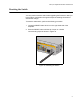
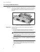
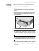
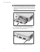
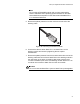


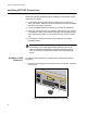
Table Of Contents
- Contents
- List of Figures
- List of Tables
- Preface
- Chapter 1
- Overview
- Chapter 2 :
- Chapter 3
- Chapter 4
- Chapter 5
- Troubleshooting
- Power LED is Off
- Twisted Pair Port Link LED is Off
- SFP or XFP LED is Off
- Transceiver is Installed but the Status is “Not Present”
- System Fault LED is Blinking
- System Fault LED is Steadily On
- Cannot Establish a Local (Out-of-Band) Management Session
- Switch Functions Intermittently
- Issues with Virtual Stacking Chassis Configuration
- Troubleshooting
- Appendix A
x600 Layer 3 Gigabit Ethernet Switch Installation Guide
75
Note
Do not cable AT-StackXG module until you have prepared the
switch’s Alliedware Plus Operating System software on the x600
Series Switches as explained in the x600 series AlliedWare Plus
5.3.1 Software Reference.
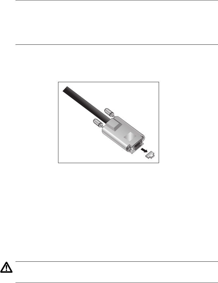
5. Remove the plastic protector from the connector at one end of the
stacking cable.
Figure 38. Removing the Plastic Protector
6. Connect the cable to either Stack Port 1 or Stack Port 2 on the
stacking module and secure by tightening the two captive
thumbscrews.
7. Remove the plastic protector from the connector at the other end of the
stacking cable and connect it to a Stack Port on the stacking module in
the next switch of the stack. A stacking cable must crossover and
connect to a different port on the next stacking module. Stack Port 1 on
a module must connect to Stack Port 2 on the next module.
Caution
Do not connect two Stack Port 1 ports or Stack Port 2 ports together.
1244