
Manual
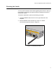
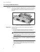
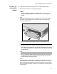
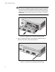
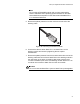

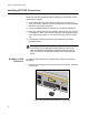
Table Of Contents
- Contents
- List of Figures
- List of Tables
- Preface
- Chapter 1
- Overview
- Chapter 2 :
- Chapter 3
- Chapter 4
- Chapter 5
- Troubleshooting
- Power LED is Off
- Twisted Pair Port Link LED is Off
- SFP or XFP LED is Off
- Transceiver is Installed but the Status is “Not Present”
- System Fault LED is Blinking
- System Fault LED is Steadily On
- Cannot Establish a Local (Out-of-Band) Management Session
- Switch Functions Intermittently
- Issues with Virtual Stacking Chassis Configuration
- Troubleshooting
- Appendix A
Chapter 3: Installing the Hardware
72
VC Stacking Module Installation
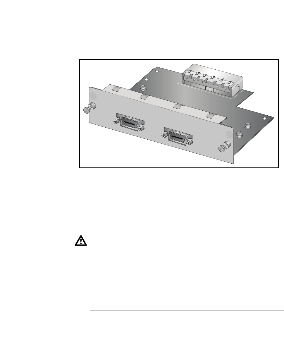
Overview When you are preparing the x600 switches for a VC Stack configuration,
the VC Stacking Module (AT-StackXG) must be installed in the expansion
slot on the rear panel of the unit. The AT-StackXG module is shown in
Figure 34.
Figure 34. VC Stacking (AT-StackXG) Module
Preparation Review the following information before installing the AT-StackXG
Stacking Module:
The AT-StackXG Stacking Module is hardware hot-swappable. You
can install or replace the module while the switch is powered on.
Caution
If the stacking module is added or replaced in an operating stack,
the stack topology may change and cause the stack to reboot and
interrupt network traffic.
The AT-StackXG module is supported in all x600 series products and
requires software version 5.3.1 or later of AlliedWare Plus Operating
System Software.
Note
Do not install AT-StackXG module until you have read the latest
version of the AW+ Software Release Notes and the x600 Series
product documentation.
1240
A
T
-LX44CPUCVR
AT-StackXG
Stack Port 1
Stac
k Port 2