
Manual
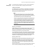

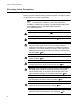
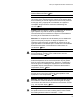
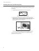
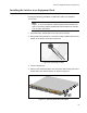
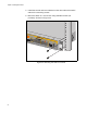
Table Of Contents
- Contents
- List of Figures
- List of Tables
- Preface
- Chapter 1
- Overview
- Chapter 2 :
- Chapter 3
- Chapter 4
- Chapter 5
- Troubleshooting
- Power LED is Off
- Twisted Pair Port Link LED is Off
- SFP or XFP LED is Off
- Transceiver is Installed but the Status is “Not Present”
- System Fault LED is Blinking
- System Fault LED is Steadily On
- Cannot Establish a Local (Out-of-Band) Management Session
- Switch Functions Intermittently
- Issues with Virtual Stacking Chassis Configuration
- Troubleshooting
- Appendix A
Chapter 3: Installing the Hardware
68
Installing the Power Cord Retaining Clip
Perform the following procedure to install the power cord retaining clip on
the switches:
1. Locate the power cord retaining clip, shown in Figure 28.
Figure 28. Power Cord Retaining Clip
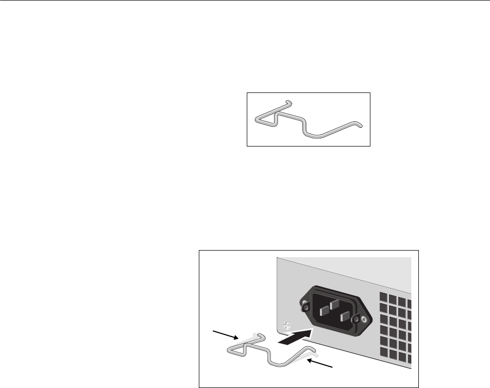
2. Install the clip on the AC power connector on the rear panel of the
switch. With the “u” of the clip facing down, press the sides of the clip
toward the center and insert the short ends into the holes in the
retaining bracket, as shown in Figure 29.
Figure 29. Inserting the Retaining Clip into the Retaining Bracket
You are now ready to install the switches in the equipment rack, as
explained in the next procedure.
100-240VAC
~