
Manual
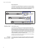
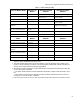
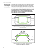
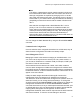
Table Of Contents
- Contents
- List of Figures
- List of Tables
- Preface
- Chapter 1
- Overview
- Chapter 2 :
- Chapter 3
- Chapter 4
- Chapter 5
- Troubleshooting
- Power LED is Off
- Twisted Pair Port Link LED is Off
- SFP or XFP LED is Off
- Transceiver is Installed but the Status is “Not Present”
- System Fault LED is Blinking
- System Fault LED is Steadily On
- Cannot Establish a Local (Out-of-Band) Management Session
- Switch Functions Intermittently
- Issues with Virtual Stacking Chassis Configuration
- Troubleshooting
- Appendix A
x600 Series Layer 3 Gigabit Ethernet Switches Installation Guide
51
VCS Stacking Modules, Cables, and Connections
The stacks are connected via the stacking ports on the VCS Stacking
Modules (AT-StackXG), which are installed in the back of each switch.
The following cables are used to connect the stacking ports of x600 series
switches:
High Speed Stacking Cables (0.5 meter) - StackXG/0.5
High Speed Stacking Cables (1.0 meter) - StackXG/1
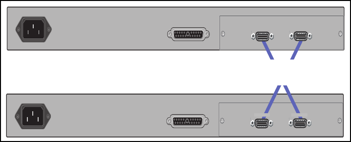
This configuration, shown in Figure 23,
uses two switches that are
connected back to back via two high-speed stacking links. Note that
stacking ports labeled 1 must connect to stacking ports labeled 2. In this
configuration the stack can still function using only a single high speed
link.
Figure 23. Back-to-Back Topology (x600 Switches)
RPS INPUT
100-240VAC~
AT-StackXG
AT-StackXG
RPS INPUT
100-240VAC~
AT-StackXG
AT-StackXG
STACK PORT 1
STACK PORT 2
STACK PORT 1 STACK PORT 2
High Speed Stacking Cables (0.5 meter)
Model Number AT-StackXG/0.5