
Manual
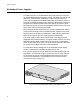
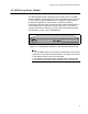

Table Of Contents
- Contents
- List of Figures
- List of Tables
- Preface
- Chapter 1
- Overview
- Chapter 2 :
- Chapter 3
- Chapter 4
- Chapter 5
- Troubleshooting
- Power LED is Off
- Twisted Pair Port Link LED is Off
- SFP or XFP LED is Off
- Transceiver is Installed but the Status is “Not Present”
- System Fault LED is Blinking
- System Fault LED is Steadily On
- Cannot Establish a Local (Out-of-Band) Management Session
- Switch Functions Intermittently
- Issues with Virtual Stacking Chassis Configuration
- Troubleshooting
- Appendix A
Chapter 1: Overview
46
VCS Stacking Module
A Virtual Chassis Stack (VCS) is a group of x600 Layer 3 Gigabit Ethernet
Series switches with a VCS Stacking module installed in each switch. The
VCS Stacking module with its two full-duplex, 12 Gbps stacking ports,
unifies the individual switches into a single, logical unit so that the network
operations of the devices encompass all of the Gigabit Ethernet ports.
This can simplify network management and augment network bandwidth.
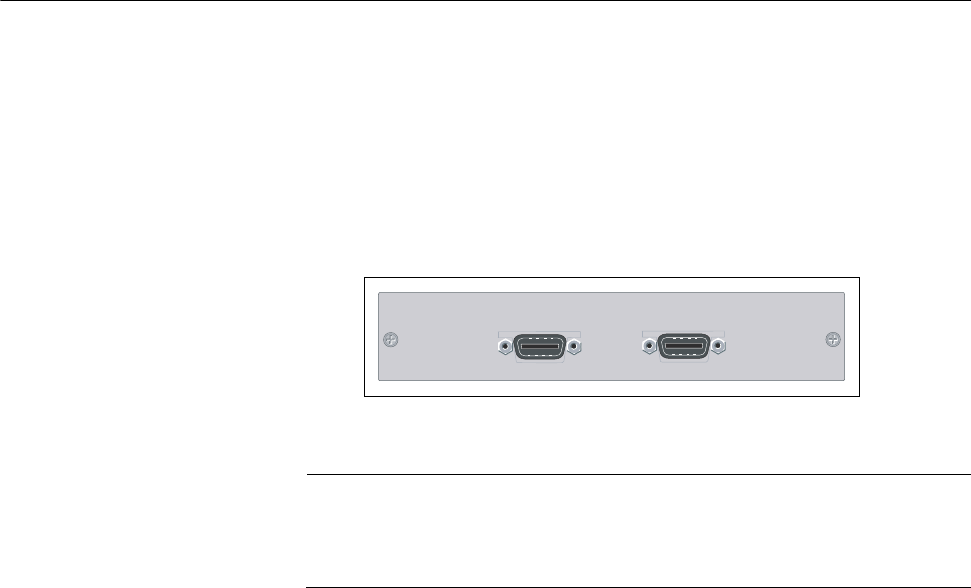
Figure 22 shows the VCS Stacking Module (AT-StackXG).
Figure 22. VCS Stacking Module (AT-StackXG)
Note
The x600-24/Ts-POE has two permanent stacking ports installed on
its rear panel. Therefore, the VCS Stacking module is not required
for this switch.
Refer to “VC Stacking Module Installation” on page 72 for the AT-StackXG
module installation instructions. For further information on stacking, refer
to the Allied Telesis Inc. website (www.alliedtelesis.com) for the Overview
of Virtual Chassis Stacking (VCS) and the Virtual Chassis Stacking
section of the AW+ Software Reference for x600 Series Switches.
AT-StackXG
STACK PORT 1
STACK PORT 2