
Manual

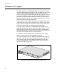
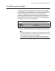
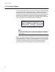


Table Of Contents
- Contents
- List of Figures
- List of Tables
- Preface
- Chapter 1
- Overview
- Chapter 2 :
- Chapter 3
- Chapter 4
- Chapter 5
- Troubleshooting
- Power LED is Off
- Twisted Pair Port Link LED is Off
- SFP or XFP LED is Off
- Transceiver is Installed but the Status is “Not Present”
- System Fault LED is Blinking
- System Fault LED is Steadily On
- Cannot Establish a Local (Out-of-Band) Management Session
- Switch Functions Intermittently
- Issues with Virtual Stacking Chassis Configuration
- Troubleshooting
- Appendix A
x600 Series Layer 3 Gigabit Ethernet Switches Installation Guide
45
AT-LBM (Loop Back) Module
The x600-48Ts/XP switch is shipped from the factory with an AT-LBM
module installed in its expansion slot on the rear panel as shown in Figure
21.This module is factory installed for the non-stacking configuration. It
provides the capability for a full line rate, nonblocking switching
configuration when there are connections on the x600-48Ts/XP switch to
all 44 copper ports, two SFP ports, and two XFP ports. If you need to
configure the switch for stacking, you may install a VC Stacking Module
(AT-StackXG) in place of the AT-LBM Module.
Figure 21. AT-LBM Module installed in x600-48Ts/XP Expansion Slot
Note
1. The AT-LBM module is very similar to a blank panel in its outward
appearance except that it is marked with the “AT_LBM” model name
in the upper left-hand corner of the faceplate.
2. The x600-24Ts, x600-24Ts/XP, and x600-48Ts are all shipped
from the factory with a blank panel installed in the expansion slot.
RPS INPUT
100-240VAC~
AT-L BM
1309