
Manual
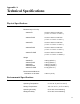

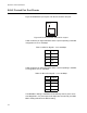
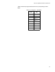
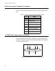
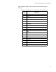
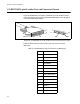
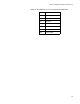

Table Of Contents
- Contents
- List of Figures
- List of Tables
- Preface
- Chapter 1
- Overview
- Chapter 2 :
- Chapter 3
- Chapter 4
- Chapter 5
- Troubleshooting
- Power LED is Off
- Twisted Pair Port Link LED is Off
- SFP or XFP LED is Off
- Transceiver is Installed but the Status is “Not Present”
- System Fault LED is Blinking
- System Fault LED is Steadily On
- Cannot Establish a Local (Out-of-Band) Management Session
- Switch Functions Intermittently
- Issues with Virtual Stacking Chassis Configuration
- Troubleshooting
- Appendix A
Appendix A: Technical Specifications
106
RJ-45 Style Serial Terminal Port Pinouts
Table 17 lists the pin signal definitions on the RJ-45 style serial terminal
port.
AT-RPS3104 17-pin Connector Pinouts
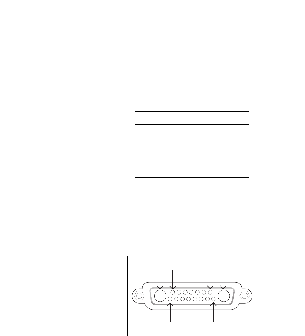
Figure 49 illustrates the pin layout of the RPS 17-pin D-combo port and
connector used to connect the AT-RPS3104 Redundant Power Supply to
the x600-24Ts-POE Switch.
Figure 49. AT-RPS3104 17-Pin Connector Layout
Table 17. RJ-45 Style Serial Terminal Port Pin Signals
Pin Signal
4 Data Carrier Detect
3 Transmit Data
6 Receive Data
7 Data Set Ready
5 Ground
2 Data Terminal Ready
8 Clear to Send
1 Request to Send
A1A2 17
15 8