
Installation Guide

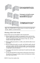
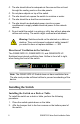

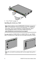
Table Of Contents

GS950PS V2 Series Quick Installation Guide 9
3. Turn over the switch.
4. Go to “Ports” on page 13.
Installing the Switch in an Equipment Rack
Here are the items for installing the switch in an equipment rack:
Two equipment rack brackets (included with the switch)
Eight M4x6mm bracket screws (included with the switch)
Cross-head screwdriver (not provided)
Four equipment rack screws (included with the switch)
To install the switch, perform the following procedure:
1. Place the switch on a table.
2. If the bumper feet are attached to the bottom panel of the switch,
remove them with a flat-head screwdriver.
3. Attach the two brackets to the sides of the switch with the eight
M3 3mm x 6mm screws included with the switch. This figure
shows the GS950/28PS V2 Switch.
4. Have another person hold the switch in the equipment rack while
you secure it using four equipment rack screws. The switch
comes with equipment rack screws.
13579111315
AT-GS950/28PS V2
Gigabit Ethernet PoE+ Switch
plus
13579111315
2 4 6 8 10 12 14 16
CLASS 1
LASER PRODUCT
POE
MAX
SYSTEM
26 28
25 27
25 27
1000 LINK
SFP
PD ERRPD ON
ACT1000 LINK
ACT100/10 LINK
PORT ACTIVITY
26 28
17 19 21 23
18 20 22 24
SFP
1357
2468
POE
9111315
10 12 14 16
17 19 21 23
18 20 22 24
100 LINK
ACT
ACT