GS950PS V2 Series Gigabit WebSmart Ethernet Switches GS950/10PS V2 GS950/18PS V2 GS950/28PS V2 GS950/52PS V2 Quick Installation Guide *613-003079 Rev A* 613-003079 Rev.
Introduction This Quick Installation Guide contains a short version of the installation instructions for the GS950PS V2 Series of Gigabit WebSmart Ethernet Switches. For complete instructions, refer to the GS950PS V2 Gigabit Ethernet Switch Series Installation Guide on the Allied Telesis web site at www.alliedtelesis.com/us/en/servicessupport.
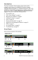
GS950/52PS V2 12 4,6 7 5 1 eco-friendly button that turns the LEDs on and off. 2 PoE MAX and POWER LEDs - GS950/10PS V2 Switch. PoE MAX and SYSTEM LEDs 3 Ethernet copper port LEDs. 4 SFP ports LEDs 5 10/100/1000Mbps Ethernet copper ports with PoE+. 6 100Mbps and 1Gbps SFP transceiver ports. 7 Ports 25 to 48 10/100/1000Mbps Ethernet copper on the GS950/52PS V2 Switch - no PoE+ Here are the 10/100/1000Mbps Ethernet copper ports.
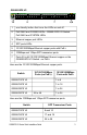
Switch SFP Transceiver Ports GS950/52PS V2 49 to 52 PoE+ Power Budgets Here are the PoE+ power budgets of the switches. Power budgets are the maximum amounts of power that PoE+ switches can supply to powered devices on the Ethernet copper ports. The switches can support IEEE 802.3at Classes 0 to 4 powered devices (maximum 30W at the ports.
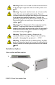
Warning: Power cord is used as a disconnection device. To de-energize equipment, disconnect the power cord. E3 Warning: To prevent electric shock, do not remove the cover. No user-serviceable parts inside. This unit contains hazardous voltages and should only be opened by a trained and qualified technician. To avoid the possibility of electric shock, disconnect electric power to the product before connecting or disconnecting the cables. E1 Warning: Class I Equipment. This equipment must be earthed.
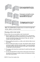
1 - Table 2 - Standard 19-inch Equipment Rack 3 - Wood or concrete wall Note: Installing the GS950/52PS V2 Switch on a wall requires the BRKT-J22 kit. The kit is sold separately. Unpacking the Switch The switches come with these items: Eight 3.5mm x 16mm wall screws and washers Eight 4mm x 22.2mm wall anchors Eight M3 3mm x 6mm bracket screws Four 10#-32T 4.
Equipment rack/wall brackets for the GS950/10PS V2 switch Equipment rack/wall brackets for the GS950/18PS V2 and GS950/28PS V2 switches Equipment rack brackets for the GS950/52PS V2 switch Note: The GS950/52PS V2 Switch does not include the eight wall screws, washers, and wall anchors. Choosing a Site for the Switch Review these site recommendations and requirements. Before installing the switch in an equipment rack, verify that the rack is safely secured so that it will not tip over.
The site should allow for adequate air flow around the unit and through the cooling vents on the side panels. Do not place objects on top of the switch. The site should not expose the switch to moisture or water. The site should be a dust-free environment. The site should use dedicated power circuits or power conditioners to supply reliable electrical power to the network devices. Do not install the switch in a wiring or utility box without adequate airflow and cooling.
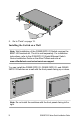
POE 2 4 6 8 10 12 14 16 18 20 22 24 26 2 28 SYSTEM 100 LINK POE MAX 1000 LINK 25 4 6 8 10 12 14 16 18 20 22 SFP 24 ACT ACT 27 26 28 SFP Gigabit Ethernet PoE+ Switch AT-GS950/28PS V2 1 3 5 7 9 11 13 15 17 19 21 23 100/10 LINK 1000 LINK plus PD ON CLASS 1 LASER PRODUCT ACT ACT PD ERR PORT ACTIVITY 1 3 5 7 9 11 13 15 17 19 21 23 25 27 3. Turn over the switch. 4. Go to “Ports” on page 13.
5. Go to “Ports” on page 13. Installing the Switch on a Wall Note: Wall installation of the GS950/52PS V2 Switch requires the BRKT-J22 brackets kit. The kit is sold separately. For installation instructions, refer to the GS950PS V2 Gigabit Ethernet Switch Series Installation Guide on the Allied Telesis web site at www.alliedtelesis.com/us/en/services-support. You can install the GS950/10PS V2, GS950/18PS V2, and GS950/ 28PS V2 Switches on a wall with the front panels facing up or down.
Here are the items for installing the switches on a wall: Two brackets and eight screws (included with switch) Four wood or concrete wall screws and washers. The switch comes with four 3.5x16mm screws and washers. Four wall anchors. The switch comes with four 4x22.2mm anchors.
Note: If you need to drill holes in the wall for the screws, perform steps 4 to 8. Otherwise, go to step 9. 4. Have a person hold the switch on the wall at the selected location while you use a pencil to mark the wall with the locations of the four screw holes in the two brackets. 5. Place the switch on a table. 6. Use a stud finder to check for hot electrical wires at the locations of the screw holes. Warning: Do not install the switch on a wall near hot electrical wires. 7.
10. Go to “Ports” next. Ports Ethernet Copper Cable Specifications The minimum cable requirements for the copper Ethernet ports are. 10Mbps or 100Mbps: Standard TIA/EIA 568-B-compliant unshielded Category 3 cabling. 1000Mbps: Standard TIA/EIA 568-A-compliant Category 5 or TIA/ EIA 568-B-compliant unshielded Enhanced Category 5 (Cat 5e) cabling.
Do not attach cables to ports of static or LACP port trunks until after configuring the switch trunks. This is to prevent the ports from forming network loops that can adversely affect network performance. PoE+ is enabled by default on the ports on the switches. Installing SFP Transceivers Here are general installation guidelines: You can install SFP transceivers while the switch is powered on.
2. Slide the transceiver into the port until it clicks into place. To attach the fiber optic cable to the transceiver, continue with the next step. Otherwise, repeat steps 1 and 2 to install the remaining transceivers in the switch. 3. Remove the dust cover from the transceiver. 4. Connect the fiber optic cable to the transceiver. The connector should fit snugly into the port, and the tab should lock the connector into place. 5. Repeat this procedure to install additional transceivers. 6.
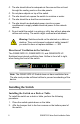
3. Plug the other end of the power cord into an appropriate AC power source. 4. Wait two minutes for the switch to start its management software. 5. Verify that the POWER LED is green. If the LED is off, see “Troubleshooting” on page 22. Starting the First Management Session This procedure explains how to start the first management session on the switch. The procedure assumes that your network has a DHCP server.
Here is the login window: 7. Enter “manager” for the User Name and “friend” for the Password. 8. Click the Sign In button. LEDs Ethernet Copper Port LEDs The LEDs for the Ethernet copper ports on the GS950/10PS V2, GS950/18PS V2, and GS950/28PS V2 Switches are on the left side of the front panels. The ports have L/A (Link/Activity) LEDs and PoE LEDs. This example is from the GS950/10PS V2 Switch.
Ports 1 to 24 Ports 25 to 48 L/A (Link/Activity) LEDs Solid green The port has established a 1Gbps link to a network device. Flashing green The port is transmitting or receiving packets at 1Gbps. Solid amber The port has established a 10 or 100Mbps link to a network device. Flashing amber The port is transmitting or receiving packets at 10 or 100Mbps. Off Possible causes of this state are listed here: - The port has not established a link with another network device. - The LEDs are turned off.
Off This LED state can result from the following conditions: - The port is not connected to a powered device or the device is powered off. - The port is disabled in the management software. - PoE+ is disabled on the port. - The LEDs are turned off. To turn on the LEDs, use the eco-friendly button. SFP Port LEDs The LEDs for the SFP ports on the GS950/10PS V2, GS950/18PS V2, and GS950/28PS V2 Switches are on the left side of the front panels. This example is from the GS950/28PS V2 Switch.
Solid amber The port has established a 100Mbps link to a network device. Flashing amber The port is transmitting or receiving packets at 100Mbps. Off Possible causes of this state are listed here: - The SFP transceiver port is empty. - The SFP transceiver is not connected to a network device or the device is powered off. - The LEDs are turned off. To turn on the LEDs, use the eco-friendly button.
POWER LED The GS950/10PS V2 Switch has a POWER LED on the left side of the faceplate. Green The switch is operating normally. Off The switch is powered off or has experienced a system failure. PoE MAX LED The switches have a PoE MAX LED on the left side of the faceplates. Off The switch is providing power to all powered devices on its ports. Red The total power requirements of the powered devices meet or exceed the switch’s maximum power budget.
Restore the default settings: Pressing the button for more than 10 seconds restores the factory default values. Note: Restoring the default settings returns the management IP address to 192.168.1.1. If your network does not have a DHCP server, you will need to change the IP address on your computer to connect to the switch again. Refer to the GS950PS V2 Gigabit Ethernet Switch Series Installation Guide.
Solution: The switch might be operating in the low power mode. To toggle on the LEDs, press the eco-friendly button on the front panel of the switch. You can also toggle the LEDs off and on with the ECOFRIENDLY LED and NO ECOFRIENDLY LED commands in the command line interface. Problem: A LINK/ACT LED is off for a Ethernet copper port that is connected to an active network device. Solutions: The port is unable to establish a link to a network device.
Copyright 2022 Allied Telesis, Inc. All rights reserved. No part of this publication may be reproduced without prior written permission from Allied Telesis, Inc. Allied Telesis and the Allied Telesis logo are trademarks of Allied Telesis, Incorporated. All other product names, company names, logos or other designations mentioned herein are trademarks or registered trademarks of their respective owners. Allied Telesis, Inc.