Broadcom Advanced Control Suite 3 User’s Guide 613-001247 Rev.
Copyright 2010 Allied Telesis, Inc. All rights reserved. No part of this publication may be reproduced without prior written permission from Allied Telesis, Inc. Microsoft and Internet Explorer are registered trademarks of Microsoft Corporation. Netscape Navigator is a registered trademark of Netscape Communications Corporation. All other product names, company names, logos or other designations mentioned herein are trademarks or registered trademarks of their respective owners. Allied Telesis, Inc.
Contents Preface .............................................................................................................................................................. 7 Safety Symbols Used in this Document ............................................................................................................. 8 Where to Find Web-based Guides ..................................................................................................................... 9 Contacting Allied Telesis .......
Contents 4
Figures Figure 1: Device Management Page ....................................................................................................................................15 Figure 2: By Connection Page..............................................................................................................................................15 Figure 3: Team Management Page ...................................................................................................................................
Figures 6
Preface This guide contains instructions on how to install and use the Broadcom Advanced Control Suite 3 for Ethernet Network adapters. The Broadcom Advanced Control Suite 3 (BACS 3) is an integrated utility that provides useful information about each network adapter that is installed in your system. BACS 3 also enables you to perform detailed tests, diagnostics, and analyses on each adapter, as well as to display and modify property values and display traffic statistics for each adapter.
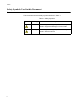
Preface Safety Symbols Used in this Document This document uses the safety symbols defined in Table 1. Table 1. Safety Symbols Symbol 8 Meaning Description Caution Performing or omitting a specific action may result in equipment damage or loss of data. Warning Performing or omitting a specific action may result in electrical shock.
Broadcom Advanced Control Suite 3 User’s Guide Where to Find Web-based Guides The installation and user guides for all Allied Telesis products are available in portable document format (PDF) on our web site at www.alliedtelesis.com/support/software. You can view the documents online or download them onto a local workstation or server.
Preface Contacting Allied Telesis This section provides Allied Telesis contact information for technical support as well as sales or corporate information. Online Support You can request technical support online by accessing the Allied Telesis Knowledge Base: www.alliedtelesis.com/support/kb.aspx. You can use the Knowledge Base to submit questions to our technical support staff and review answers to previously asked questions.
Chapter 1 Starting and Using BACS 3 This chapter provides detailed information about the minimum and recommended .NET Framework versions for BACS3. In addition, this chapter describes how to set the BACs software.
Chapter 1: Starting and Using BACS 3 Starting Broadcom Advanced Control Suite 3 Microsoft .NET Framework 2.0 includes the runtime and associated files needed to run BACS 3, and must be installed on your system in order for BACS 3 to operate. For information on the minimum and recommended .NET Framework versions for your operating system, see Table 1. Note Starting BACS 3 without .NET Framework (version 2.0 or above) installed on your system results in an error.
Broadcom Advanced Control Suite 3 User’s Guide Table 1. .NET Framework Versions for BACS 3 (Continued) Minimum Required Recommended Operating System Version How to Obtain Version How to Obtain Windows Vista .NET 2.0 Included in .NET 3.0 which is included during OS installation .NET 2.0 SP1 Download Vista SP1 from Microsoft which includes .NET 2.0 SP1 Windows Server 2008 .NET 2.0 Included in .NET 2.0 SP1, which is included during OS installation .NET 2.
Chapter 1: Starting and Using BACS 3 Using Broadcom Advanced Control Suite 3 To start BACS 3, click Broadcom Control Suite 3 in the Control Panel. Click the tab that provides the information of interest such as to perform a desired test, diagnostic, analysis, or set adapter properties. To create a team, see Chapter 2, “Configuring Teaming” on page 43. Using the Interface BACS 3 features a context-sensitive interface.
Broadcom Advanced Control Suite 3 User’s Guide Figure 1. Device Management Page To list items in Device Management by connection, do the following: At the top of the Device Management pane, click By Connection. The By Connection Page is displayed. See Figure 2 on page 15. The Connection View lists the server and client devices in a parent/child hierarchy, which makes it easier to see the relationships between the adapters.
Chapter 1: Starting and Using BACS 3 Device Icons The icon next to each device in the Device Management pane shows its status. An icon next to a device name that appears normal means the device is connected and working. Two additional states may occur: X. A red "X" that appears on the device's icon indicates the device is currently not connected to the network. Greyed out. A device icon that appears greyed out indicates the device is currently disabled.
Broadcom Advanced Control Suite 3 User’s Guide Configuring BACS User Interface Options This section describes how to enable and disable the BACS Tray icon. After the program is installed, BACS 3 places an icon in the Windows taskbar. Use the Options window to turn this icon on or off. To enable or disable the BACS tray icon, do the following: 1. From the Tools menu, select Options. 2. In the Options window, select General. 3. Select or clear Enable Tray Icon. The option is enabled by default. 4. Click OK.
Chapter 1: Starting and Using BACS 3 If the Vital Signs section within the Information tab is not visible, do the following. From the Context View tab on the right side of the window, select Information. Then, select Vital Signs. Note Information about Allied Telesis or Broadcom-based network adapters may be more comprehensive than information about network adapters made by other vendors. Note Some information may not be available for all Allied Telesis or Broadcom-based network adapters. Figure 4.
Broadcom Advanced Control Suite 3 User’s Guide Link Status The Link Status indicates the status of the network link. There are two states: Up. A link is established. Down. A link is not established. Duplex The adapter is operating in the indicated duplex mode. Speed The link speed of the adapter in megabits per second. Offload Capabilities The offload capabilities supported by the adapter. This information is only available for Allied Telesis AT-2973 adapters. LSO.
Chapter 1: Starting and Using BACS 3 Viewing Driver Information The Driver Information section of the Information tab displays data about the driver for the selected network adapter. To view Driver Information for any installed network adapter, click the name of the adapter listed in the Device Management pane, then click the Information tab. The Driver Information Page is displayed. See Figure 5.
Broadcom Advanced Control Suite 3 User’s Guide Displaying Resource Information The Resources section of the Information tab displays information about connections and other essential functions for the selected network adapter. To view Resources for any installed network adapter, click the name of the adapter listed in the Device Management pane, then click the Information tab. The Resources Page is displayed. See Figure 6 on page 21.
Chapter 1: Starting and Using BACS 3 Slot No Indicates the slot number on the system board occupied by the adapter. This item is not available for PCI Express type adapters. Bus Speed (MHz) Indicates the bus clock signal frequency used by the adapter. This item is not available for PCI Express type adapters. Bus Width (bit) Indicates the number of bits that the bus can transfer at a single time to and from the adapter. This item is not available for PCI Express type adapters.
Broadcom Advanced Control Suite 3 User’s Guide To view Hardware for any installed network adapter, click the name of the adapter listed in the Device Management pane, then click the Information tab. The Hardware Information Page is displayed. See Figure 7. If the Information tab is not visible, then from the View menu, select Navigate, Device Management, and Information.
Chapter 1: Starting and Using BACS 3 Subsystem Vendor ID Indicates the subsystem vendor ID. Subsystem ID Indicates the subsystem ID. Testing the Network The Network Test option on the Diagnostics tab lets you verify IP network connectivity. This test verifies if the driver is installed correctly and tests connectivity to a gateway or other specified IP address on the same subnet. The network test uses TCP/IP to send ICMP packets to remote systems, then waits for a response.
Broadcom Advanced Control Suite 3 User’s Guide 5. Click Run. The results of the network test are displayed in the Result field of Figure 8. Figure 8. Network Test Page Running Diagnostic Tests The Diagnostic Tests option on the Diagnostics tab lets you check the state of the physical components on a Allied Telesis or Broadcom-based network adapter. You can trigger the tests manually, or choose to have BACS 3 continuously perform them.
Chapter 1: Starting and Using BACS 3 3. From the Select a test to run list, select Diagnostic Tests. If the Diagnostic Tests option is not available, then from the Context View tab on the right side of the window, select Diagnostics and then select Diagnostic Tests. The Diagnostics Test Page is displayed. See Figure 9 on page 26. 4. Select the diagnostic tests you want to run. Click Select All to select all tests or Clear All to clear all test selections. 5. Click Run. 6.
Broadcom Advanced Control Suite 3 User’s Guide 7. In the error message window that warns of the network connection being temporarily interrupted, click Yes. The diagnostic tests run continuously and the Status field for each test displays the accumulated total of passes and failures. 8. To stop the continuous testing, click Abort. Control Registers This test verifies the read and write capabilities of the network adapter registers by writing various values to the registers and verifying the results.
Chapter 1: Starting and Using BACS 3 Test LED This test causes all of the port LEDs to blink 5 times for the purpose of identifying the adapter. Analyzing Cables The Cable Analysis option on the Diagnostics tab lets you monitor the conditions of each wire pair in an Ethernet Category 5 cable connection within an Ethernet network. The analysis measures the cable quality and compares it against the IEEE 802.3ab specification for compliance.
Broadcom Advanced Control Suite 3 User’s Guide 6. In the error message window that warns of the network connection being temporarily interrupted, click Yes. Figure 10. Cable Analysis Page Distance The valid cable length in meters (except when the Noise result is returned).
Chapter 1: Starting and Using BACS 3 Status The result of the analysis for the indicated pair can be one of the following: Good. Good cable/PCB signal paths, but no gigabit link. Crossed. Pin short or crosstalk along two or more cable/PCB signal paths. Open. One or both pins are open for a twisted pair. Short. Two pins from the same twisted pair are shorted together. Noise. Persistent noise present (most likely caused by Forced 10/ 100). GB Link. Gigabit link is up and running.
Broadcom Advanced Control Suite 3 User’s Guide To set adapter properties, do the following: 1. Click the name of the adapter in the Device Management pane. 2. Click the Configurations tab. If the Configurations tab is not visible, then from the View menu, select Navigate, Device Management, and Configurations. 3. From the Advanced section, select the property you want to set.
Chapter 1: Starting and Using BACS 3 Figure 11. Advanced Page 802.1p QOS Enables the quality of service (QoS) feature, which is an Institute of Electrical and Electronics Engineering (IEEE) specification that treats different types of network traffic diversely to ensure required levels or reliability and latency according to the type of traffic. This property is disabled by default. Unless the network infrastructure supports QoS, do not enable this property. Otherwise, problems may occur.
Broadcom Advanced Control Suite 3 User’s Guide Flow Control Enables or disables the receipt or transmission of PAUSE frames. PAUSE frames allow the network adapter and a switch to control the transmit rate. The side that is receiving the PAUSE frame momentarily stops transmitting. Select one of the following: Auto (default). PAUSE frame receipt and transmission are optimized. Disable. PAUSE frame receipt and transmission are disabled. Rx PAUSE. PAUSE frame receipt is enabled. Rx/Tx PAUSE.
Chapter 1: Starting and Using BACS 3 LSO & Jumbo Frames Enables the network adapter to transmit and receive oversized Ethernet frames that are greater than 1514 bytes, but less than 9000 bytes in length. This property requires the presence of a switch that is able to process Jumbo frames. This information is available for some Broadcom NetXtreme adapters. Frame size is set at 1500 bytes by default by selecting the LSO Enabled, Jumbo Off option.
Broadcom Advanced Control Suite 3 User’s Guide The appropriate assigned ranges and exceptions for the locally administered address include the following: The range is 00:00:00:00:00:01 to FF:FF:FF:FF:FF:FD. Do not use a multicast address (least significant bit of the high byte = 1). Do not use all 0s or all Fs. Receive Side Scaling Allows configuring network load balancing across multiple CPUs. The default setting for this property is Enabled.
Chapter 1: Starting and Using BACS 3 Note 10 Mb Half and 100 Mb Half settings force the network adapter to connect to the network in Half-Duplex mode. Note that the network adapter may not function if the network is not configured to operate at the same mode. Note 10 Mb Full and 100 Mb Full settings force the network adapter to connect to the network in Full-Duplex mode. The network adapter may not function if the network is not configured to operate at the same mode.
Broadcom Advanced Control Suite 3 User’s Guide WOL Speed Sets the speed at which the network adapter connects to the network while the network adapter is in Wake on LAN mode. By default, the WOL Speed property is set to Auto. This property is only available for Broadcom NetXtreme adapters. 10 Mb. Sets the speed to 10 Mbit/s. This is the network speed when the system is in a standby mode awaiting a wake-up frame. 100 Mb. Sets the speed to 100 Mbit/s. Auto (default).
Chapter 1: Starting and Using BACS 3 Displaying Statistics The information provided on the Statistics tab allows you to display traffic statistics for Allied Telesis, Broadcom-based network adapters, and network adapters made by other vendors. Statistical information and coverage are more comprehensive for Allied Telesis and Broadcom-based adapters.
Broadcom Advanced Control Suite 3 User’s Guide Figure 12. General Statistics Page Directed Frames Tx A count of directed data frames that were successfully transmitted. Multicast Frames Tx A count of frames that were successfully transmitted (as indicated by the status value Transmit OK) to a group destination address other than a broadcast address. Broadcast Frames Tx A count of frames that were successfully transmitted (as indicated by the transmit status Transmit OK) to the broadcast address.
Chapter 1: Starting and Using BACS 3 transmitted to multicast addresses are not broadcast frames and are excluded. Directed Frames Rx A count of directed data frames that were successfully received. Multicast Frames Rx A count of frames that were successfully received and are directed to an active nonbroadcast group address. This does not include frames received with frame-too-long, FCS, length, or alignment errors, nor frames lost because of internal MAC sublayer errors.
Broadcom Advanced Control Suite 3 User’s Guide Frames Tx after Deferral. A count of the frames that were delayed being transmitted on the first attempt because the medium was busy. The frames involved in any collision are not counted. Custom Statistics This section describes the Custom Statistics portion of the General Statistics page which appears in Figure 12 on page 39. Note Custom statistics are available only for an enabled Allied Telesis or Broadcom-based network adapter. Out of Recv. Buffer.
Chapter 1: Starting and Using BACS 3 42
Chapter 2 Configuring Teaming The teaming function allows you to group any available network adapters together to function as a team. Teaming is a method of creating a virtual NIC which is a group of multiple adapters that functions as a single adapter. The benefit of this approach is that it enables load balancing and failover. Teaming is done through the Broadcom Advanced Server Program (BASP) software.
Chapter 2: Configuring Teaming Note The TCP Offload Engine (TOE), Large Send Offload (LSO), and Checksum Offload properties are enabled for a team only when all of the members support and are configured for the feature. Note You must have administrator privileges to create or modify a team.
Broadcom Advanced Control Suite 3 User’s Guide Defining Team Types You can create four types of load balance teams: Smart Load Balance and Failover Smart Load Balance and Failover Link Aggregation (802.3ad) Generic Trunking (FEC/GEC)/802.3ad-Draft Static SLB (Auto-Fallback Disable) – The Auto-Fallback Disable feature is configured for Smart Load Balance and Failover type teams in the Teaming Wizard.
Chapter 2: Configuring Teaming Load Balancing and Failover type of team in which auto-fallback occurs. In addition, the LiveLink feature is supported for the SLB team. Standby Team Member and Auto-Fallback Disable Mode You can designate one team member in an SLB team as the standby member. The standby member does not actively send and receive normal network traffic while other adapters on the team are active.
Broadcom Advanced Control Suite 3 User’s Guide Using the Broadcom Teaming Wizard To use the Broadcom Teaming Wizard to create a team, configure an existing team, or create a VLAN, do the following: 1. Click the Team Management button at the bottom of the BACS 3 window, or from the View menu, select Navigate, then Team Management. 2. Click Teams at the top of the Team Management pane, or select one of the listed adapters. 3.
Chapter 2: Configuring Teaming Figure 14. Edit Team Path Note If you prefer to work without the wizard, click Expert Mode. If you want to always use Expert Mode to create a team, select Default to Expert Mode on next start. See “Using the Expert Mode” on page 65. 5. To continue using the wizard, click Next on the Broadcom Teaming Wizard Page. See Figure 15 on page 49.
Broadcom Advanced Control Suite 3 User’s Guide Figure 15. Broadcom Teaming Wizard Page 6. Type the team name and then click Next. If you want to review or change any of your settings, click Back. Click Cancel to discard your settings and exit the wizard. The Creating/Modifying a Team: Team Name Page is displayed. See Figure 16 on page 50.
Chapter 2: Configuring Teaming Figure 16. Creating/Modifying a Team: Team Name Page 7. Select the type of team you want to create. If the team type is an SLB type team, click Next. If the team type is not an SLB type team, then a dialog box appears. 8. Verify that the network switch connected to the team members is configured correctly for the team type, click OK, and continue. The Creating/Modifying a Team: Team Type Page is displayed. See Figure 17 on page 51.
Broadcom Advanced Control Suite 3 User’s Guide Figure 17. Creating/Modifying a Team: Team Type Page 9. From the Available Adapters list, click the adapter you want to add to the team and then click Add. Remove team members from the Team Members list by clicking the adapter and then clicking Remove. Click Next. The Creating/Modifying a Team: Assigning Team Members Page is displayed. See Figure 18 on page 52. Note There must be at least one Broadcom network adapter assigned to the team.
Chapter 2: Configuring Teaming support and are configured for the feature. If this is the case, then the team offload capabilities appear on the bottom of the screen. Note Adding a network adapter to a team where its driver is disabled may negatively affect the offloading capabilities of the team which, in turn, may have an impact on the team's performance. Therefore, it is recommended that only driver-enabled network adapters are added as members to a team. Figure 18.
Broadcom Advanced Control Suite 3 User’s Guide The Creating/Modifying a Team: Designating a Standby Member Page is displayed. See Figure 19. Figure 19. Creating/Modifying a Team: Designating a Standby Member Page 12. If you want to configure LiveLink, select Yes, otherwise select No, then click Next. The Creating/Modifying a Team: Configuring LiveLink Page is displayed. See Figure 20 on page 54.
Chapter 2: Configuring Teaming Figure 20. Creating/Modifying a Team: Configuring LiveLink Page 13. Select the probe interval (the number of seconds between each retransmission of a link packet to the probe target) and the maximum number of probe retries (the number of consecutively missed responses from a probe target before a failover is triggered). 14. Set the Probe VLAN ID to allow for connectivity with probe targets residing on a tagged VLAN.
Broadcom Advanced Control Suite 3 User’s Guide 15. Click the probe target at the top of the list, click Edit Target IP Address, type the target IP address in the IP Address box for one or all probe targets, and then click OK. Click Next. The Creating/Modifying a Team: Configuring LiveLink Page (continued 2) is displayed. See Figure 22 on page 56. Note Only the first probe target is required.
Chapter 2: Configuring Teaming Note All of the member IP addresses must be in the same subnet as the subnet of the probe targets. Figure 22. Creating/Modifying a Team: Configuring LiveLink Page (continued 2) 17. If you want to create a VLAN on the team, select Add VLAN, or if you want to change the settings of an existing VLAN, select Edit VLAN, then click Next. The Creating/Modifying a VLAN: Configure VLAN Support Page is supported. See Figure 23 on page 57.
Broadcom Advanced Control Suite 3 User’s Guide Note VLANs can only be created when all team members are Broadcom adapters. Figure 23. Creating/Modifying a VLAN: Configure VLAN Support Page 18. Type the VLAN name and then click Next.
Chapter 2: Configuring Teaming Figure 24. Creating/Modifying a VLAN: Naming Page 19. To tag the VLAN, select Tagged and then click Next. Otherwise, click Untagged, click Next, and continue with the wizard to add additional VLANs (see step 21 of this procedure). The Creating/Modifying a VLAN: Tagging Page is displayed. See Figure 25 on page 59.
Broadcom Advanced Control Suite 3 User’s Guide Figure 25. Creating/Modifying a VLAN: Tagging Page 20. Type the VLAN tag value and then click Next. The value must be between 1 and 4094. The Creating/Modifying a VLAN: Tag Value Page is displayed. See Figure 26 on page 60.
Chapter 2: Configuring Teaming Figure 26. Creating/Modifying a VLAN: Tag Value Page 21. Select Yes to add or manage another VLAN and then click Next. Repeat until you do not want to add or manage any additional VLANs. The Creating/Modifying a VLAN: Additional VLANs Page is displayed. See Figure 27 on page 61. Note You can define up to 64 VLANs per team (63 VLANs that are tagged and 1 VLAN that is not tagged).
Broadcom Advanced Control Suite 3 User’s Guide Figure 27. Creating/Modifying a VLAN: Additional VLANs Page 22. To apply and commit the changes to the team, select Commit changes to system and Exit the wizard. To apply your changes but continue using the wizard, select Save changes and continue to manage more teams. Click Finish. The Congratulations! Page is displayed. See Figure 28 on page 62.
Chapter 2: Configuring Teaming Figure 28.
Broadcom Advanced Control Suite 3 User’s Guide Note At any point in the Broadcom Teaming Wizard procedure, click Preview to get a visual representation of what the team will look like before committing any changes. Figure 29. Broadcom Teaming Wizard: Commit Changes Page 23. Click the team name in the Team Management pane to view the team's properties in the Information tab, transfer and receive data in the Statistics tab, and team customization options in the Configurations tab.
Chapter 2: Configuring Teaming Figure 30.
Broadcom Advanced Control Suite 3 User’s Guide Using the Expert Mode Use Expert Mode to do the following team activities: “Creating a Team” on page 65 “Modifying a Team” on page 70 “Displaying VLANs and Running VLAN Tests” on page 73 “Configuring LiveLink” on page 74 To set the default Teaming Mode to Expert Mode, select Options from the Tools menu. In the Options window, click the General tab, then select Expert Mode. The default is Wizard Mode.
Chapter 2: Configuring Teaming This option is not available if there are no devices listed in the "Unassigned Adapters" sections, which means all adapters are already assigned to teams. Figure 31. Creating A Team Path 4. Click Expert Mode. The Manage Teams Page: Create Team Tab is displayed. See Figure 32 on page 66. If you want to always use Expert Mode to create a team, click Default to Expert Mode on next start. Figure 32.
Broadcom Advanced Control Suite 3 User’s Guide 5. Click the Create Team tab. The Manage Load Balance Members Page is displayed. See Figure 32. Note The Create Team tab appears only if there are team-ready adapters available. 6. Click the Team Name field to enter a team name. 7. Click the Team Type field to select a team type. 8. Click Manage Members at the top of the window. The Manage Load Balance Members Window is displayed. See Figure 33. Figure 33. Manage Load Balance Members Window 9.
Chapter 2: Configuring Teaming Note You must assign at least one Allied Telesis or Broadcom-based network adapter to the team. The TCP Offload Engine (TOE), Large Send Offload (LSO), and Checksum Offload (CO) columns indicate if the TOE, LSO, and the CO properties are supported (Y) or not supported (N) for the adapter. The TOE, LSO, and CO properties are enabled for a team only when all of the members support and are configured for the feature.
Broadcom Advanced Control Suite 3 User’s Guide Note The maximum number of team members is 8. Note When team configuration has been correctly performed, a virtual team adapter driver is created for each configured team. Note If you disable a virtual team and later want to reenable it, you must first disable and reenable all team members before you reenable the virtual team. Note When you create Generic Trunking and Link Aggregation teams, you cannot designate a standby member.
Chapter 2: Configuring Teaming d. Configure the IP address and any other necessary TCP/IP configuration for the team, and then click OK when finished. Modifying a Team After you have created a team, you can modify the team in the following ways: Change the type of team Change the members assigned to the team Add a VLAN Modify a VLAN (using Expert Mode) Remove a team or a VLAN (using Expert Mode) To modify a team, do the following: 1.
Broadcom Advanced Control Suite 3 User’s Guide 5. Click the Edit Team tab. The Manage Teams Page: Edit Team Tab is displayed. See Figure 35. Figure 35. Manage Teams Page: Edit Team Tab 6. Make the desired changes, and then click Update. The changes have not yet been applied; click the Preview tab to view the updated team structure before proceeding to the next step to apply the changes. 7. Click Apply/Exit to apply the updates and exit the Manage Teams window. 8.
Chapter 2: Configuring Teaming Adding a VLAN You can add virtual LANs (VLANs) to a team. This enables you to add multiple virtual adapters that are on different subnets. The benefit of having multiple virtual adapters is that your system can have one network adapter that can belong to multiple subnets. With a VLAN, you can couple the functionality of load balancing for the load balance members, and you can employ a failover adapter.
Broadcom Advanced Control Suite 3 User’s Guide Figure 36. Manage VLAN(s) Page 9. Click Yes when the message is displayed indicating that the network connection will be temporarily interrupted. Note To maintain optimum adapter performance, your system should have 64 MB of system memory for each of the eight VLANs created per adapter. Displaying VLANs and Running VLAN Tests This section discusses how to display VLAN Properties and statistics as well as how to delete VLANs.
Chapter 2: Configuring Teaming Deleting a VLAN To delete a VLAN in Expert Mode, do the following: 1. Click the Team Management button at the bottom of the BACS 3 window, or from the View menu, select Navigate, then Team Management. 2. Select the VLAN to delete. 3. From the Teams menu, select Remove VLAN. 4. Click Apply. 5. Click Yes when the message is displayed indicating that the network connection will be temporarily interrupted.
Broadcom Advanced Control Suite 3 User’s Guide Note You can specify up to four probe targets. Note The IP address assigned to either a probe target or team member cannot have a zero as the first or last octet. To configure LiveLink, do the following: 1. Click the Team Management button at the bottom of the BACS 3 window, or from the View menu, select Navigate, then Team Management. 2. Select the Smart Load Balance and Failover or SLB (Auto-Fallback Disable) team. 3. From the Teams menu, select Edit Team.
Chapter 2: Configuring Teaming To specify different values, click the desired probe interval in the Probe interval (seconds) list and click the desired maximum number of probe retries in the Probe maximum retries list. Figure 37. Manage Teams Page: Edit Teams Tab 7. Set the Probe VLAN ID to correspond with the VLAN where the probe target(s) resides. This step applies the appropriate VLAN tag to the link packet based on the shared configuration of the attached switch port(s).
Broadcom Advanced Control Suite 3 User’s Guide Note Only the first probe target is required. You can specify up to 3 additional probe targets to serve as backups by assigning IP addresses to the other probe targets. 9. Select one of the listed team members and type the member IP address. Note All of the member IP addresses must be in the same subnet as the probe targets. 10. Click Update. Repeat these steps for each of the other listed team members. 11. Click Apply/Exit.
Chapter 2: Configuring Teaming Saving and Restoring the Configuration This section provides procedures to save and restore the teaming configuration. To save the configuration, do the following: 1. From the File menu, select Team Save As. 2. Type the path and file name of the new configuration file, and then click Save (a .bcg extension is added). The configuration file is a text file that can be viewed with any text editor. This file contains information about both the adapter and the team configuration.
Broadcom Advanced Control Suite 3 User’s Guide Viewing BASP Statistics The BASP Statistics section displays performance information about the network adapters that are on a team. To display BASP Statistics information for any team member adapter or the team as a whole, click the name of the adapter or team listed in the Team Management pane, then click the Statistics tab.
Chapter 2: Configuring Teaming Figure 38.