
Specifications
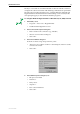


20 AT-8800 Series Switch
C613-03066-00 REV D
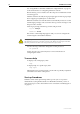
Pin assignments
For twisted pair cables each pair is identified by two different colours. For
example, one wire might be red, and the other red with a white stripe. An RJ-45
connector must be fitted to both ends of the cable. Figure 8 on page 20
illustrates the pin layout for RJ-45 connectors.
Figure 8: RJ-45 Pin layout.
1000BASE straight through cable
For 1000BASE network connections, all four pairs are used and the cable is
wired in a straight-through configuration. This cable can also be used, in
conjunction with the software test facility, to test 1000BASE network ports.
Table 7 on page 20 lists the pin assignments.
1000BASE crossover cable
For 1000BASE test cables, all four pairs are used and the cable is wired in either
a crossover or straight-through configuration. Table 8 on page 21 lists the pin
assignments for a crossover cable.
Table 7: Pin assignments, 10/100/1000BASE-T RJ-45 four pair straight-through
cable.
End 1 End 2
Pin Pair Pin Pair
1 Pair 1+ 1 Pair 1+
2 Pair 1- 2 Pair 1-
3 Pair 2+ 3 Pair 2+
6 Pair 2- 6 Pair 2-
4 Pair 3+ 4 Pair 3+
5 Pair 3- 5 Pair 3-
7 Pair 4+ 7 Pair 4+
8 Pair 4- 8 Pair 4-
1
8
1
8
RJPIN