
Specifications


18 AT-8800 Series Switch
C613-03066-00 REV D
Useful Cables
This section describes how to make management, test, and network cables for
use with the switch’s RS-232 (ASYN0) and RJ-45 interfaces.
RS-232 Terminal and Modem Cables
Table 5 on page 18 list the terminal and modem cables described in this section.
Figure 6 on page 18, and Figure 7 on page 19 show how to wire cables to
connect a standard VT100 compatible terminal, or a modem, to ASYN0.
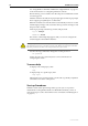
Figure 6: Pin wiring diagram for a standard DB9 male to female terminal cable.
Table 5: Terminal and modem cable descriptions.
Cable type Description
RS-232 RJ-45 to DB9 female terminal cable Figure 6 on page 18
RS-232 RJ-45 to DB9 male modem cable Figure 7 on page 19
Notes:
(1) → Output from switch; ← Input to switch.
(2) Cable version 1.0.
(3) Pin 4 unconnected.
RJ-45
(to switch/DTE)
DE9 Female
(to PC/terminal/DTE)
Ciscowiredrj45db9
(DTR)
2
(RXD)
(TXD)
3
6
(DCD)
7
(GND) 5
(CTS) 8
(RTS)
1
not connected
1
2
3
4
5
6
7
8
9
(DCD)
(RXD)
(TXD)
(DTR)
(GND)
not connected
(DSR)
(RTS)
(CTS)
(RING)
Cable
Pin 9
Pin 6
Pin 5
Pin 1
DB9 Female Pin View
1
8
RJ-45 Pin View