
User Manual


Table Of Contents
- Contents
- Figures
- Tables
- Preface
- Chapter 1
- Overview
- Chapter 2
- Installation
- Reviewing Safety Precautions
- Cable Requirements
- Unpacking the AT-MCF2000M Management Module
- Setting the Chassis ID Jumper
- Installing the Management Module
- Cabling a Media Converter Stack
- Verifying the Installation
- Starting a Local Management Session
- Removing the AT-MCF2000M Management Module
- Installing a Media Converter Module
- Chapter 3
- Troubleshooting
- Appendix A
- Technical Specifications
Appendix A: Technical Specifications
70
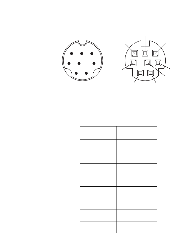
RS-232 Terminal Port Pinouts
Figure 23 illustrates the pin layouts for the DIN-8 connector
and port of the RS-232 Terminal port.
Figure 23. RS-232 Terminal Port Pinouts
Table 12 lists the pin signals for the RS-232 Terminal port.
Table 12. RS-232 Terminal Port
Pin Signal
1NC
2DTR
3TX
4RX
5DSR
6GND
7RTS
8CTS
12
34 5
678
21
3
4
5
6
7
8
158