
User Manual


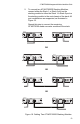


Table Of Contents
- Contents
- Figures
- Tables
- Preface
- Chapter 1
- Overview
- Chapter 2
- Installation
- Reviewing Safety Precautions
- Cable Requirements
- Unpacking the AT-MCF2000M Management Module
- Setting the Chassis ID Jumper
- Installing the Management Module
- Cabling a Media Converter Stack
- Verifying the Installation
- Starting a Local Management Session
- Removing the AT-MCF2000M Management Module
- Installing a Media Converter Module
- Chapter 3
- Troubleshooting
- Appendix A
- Technical Specifications
AT-MCF2000M Management Module Installation Guide
53
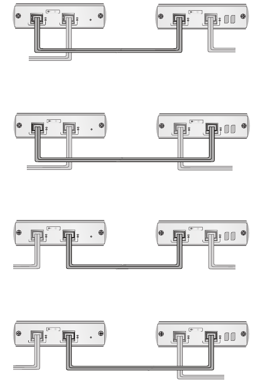
2. To connect two AT-MCF2000S Stacking Modules,
connect either the Stack 1 or Stack 2 port on the
stacking module to either the Stack 1 or Stack 2 port on
the stacking module in the next chassis of the stack. All
port combinations are supported, as illustrated in
Figure 19.
Repeat this step to connect the remaining
AT-MCF2000 media converter modules to the stack.
Figure 19. Cabling Two AT-MCF2000S Stacking Modules
AT-MCF2000S
POWER
LINK ACT
PORT ACTIVITY
STACK 1 STACK 2
AT-MCF2000S
LINK ACT
PORT ACTIVITY
STACK 1 STACK 2
AT-MCF2000S
POWER
LINK ACT
PORT ACTIVITY
STACK 1 STACK 2
AT-MCF2000S
LINK ACT
PORT ACTIVITY
STACK 1 STACK 2
AT-MCF2000S
AT-MCF2000S
POWER
LINK ACT
PORT ACTIVITY
STACK 1 STACK 2
LINK ACT
PORT ACTIVITY
STACK 1 STACK 2
AT-MCF2000S
POWER
LINK ACT
PORT ACTIVITY
STACK 1 STACK 2
AT-MCF2000S
LINK ACT
PORT ACTIVITY
STACK 1 STACK 2
CHASSIS ID
CHASSIS ID
CHASSIS ID
CHASSIS ID
OR
OR
OR