
User Manual


Table Of Contents
- Contents
- Figures
- Tables
- Preface
- Chapter 1
- Overview
- Chapter 2
- Installation
- Reviewing Safety Precautions
- Cable Requirements
- Unpacking the AT-MCF2000M Management Module
- Setting the Chassis ID Jumper
- Installing the Management Module
- Cabling a Media Converter Stack
- Verifying the Installation
- Starting a Local Management Session
- Removing the AT-MCF2000M Management Module
- Installing a Media Converter Module
- Chapter 3
- Troubleshooting
- Appendix A
- Technical Specifications
AT-MCF2000M Management Module Installation Guide
49
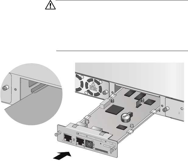
3. Align the edges of the module with the guides in the
slot and carefully slide the module into the chassis until
it is flush with the front of the chassis. Refer to Figure
15. Light pressure may be necessary to firmly seat the
module connector on the connector on the back panel
of the chassis.
Caution
Do not force the module into place. Doing so may
damage the connector pins on the backplane of the
chassis. If there is resistance, remove the module and
reinsert it after verifying that the edges of the card are
properly aligned in the guides in the chassis’ module
slot.
Figure 15. Installing the Management Module
AT-MCF2KFA
N
NORMA
L
FAULT
STA
TU
S
A
T
-M
C
F2000M
S
TA
C
K
M
A
N
AG
E
M
E
N
T
T
E
R
M
IN
A
L
1
0
/1
0
0
/1
0
0
0
B
A
S
E
-
T
R
S
-2
3
2
R
E
S
E
T
S
D
R
D
Y
B
U
S
Y
M
A
S
T
E
R
P
O
W
E
R
B
O
O
T
R
D
Y
F
A
U
L
T
1
0
0
0
L
IN
K
A
C
T
1
0
/1
0
0
L
IN
K
A
C
T
F
D
X
H
D
X
C
O
L
L
IN
K
A
C
T
PO
R
T
A
CTIVITY
1200a