
User Manual


Table Of Contents
- Contents
- Figures
- Tables
- Preface
- Chapter 1
- Overview
- Chapter 2
- Installation
- Reviewing Safety Precautions
- Cable Requirements
- Unpacking the AT-MCF2000M Management Module
- Setting the Chassis ID Jumper
- Installing the Management Module
- Cabling a Media Converter Stack
- Verifying the Installation
- Starting a Local Management Session
- Removing the AT-MCF2000M Management Module
- Installing a Media Converter Module
- Chapter 3
- Troubleshooting
- Appendix A
- Technical Specifications
AT-MCF2000M Management Module Installation Guide
35
10/100/
1000Base-T
Management
Port LEDs
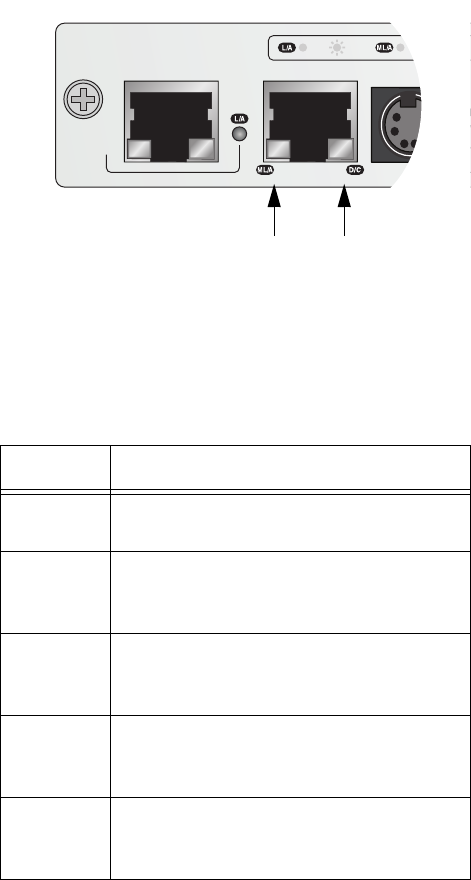
The 10/100/1000Base-T Management port has a L/A (Link/
Activity) LED and a D/C (Duplex-mode/Collisions) LED.
Figure 9. Link/Activity and Duplex-mode LEDs on the
Management Port
The states of the Link/Activity LED are defined in Table 4.
Table 4. Link/Activity LED on the Management Port
State Description
Off The port has not established a link with a
network device.
Steady
Green
The port has established an 1000 Mbps
link with a network device, but is not
forwarding or receiving network packets.
Flashing
Green
The port has established an 1000 Mbps
link with a network device and is
forwarding or receiving network packets.
Steady
Amber
The port has established a 10 or 100 Mbps
link with a network device, but is not
forwarding or receiving network packets.
Flashing
Amber
The port has established a 10 or 100 Mbps
link with a network device and is
forwarding or receiving network packets.
AT-MCF2000M
STACK MANAGEMENT
TERMINAL
10/100/1000BASE-T
RS-232
1000 LINK A
C
LINK ACT
1199b
Link/Activity
LED
Duplex-mode/
Collisions LED