Management Module AT-MCF2000M Installation Guide 613-000709 Rev.
Copyright © 2008 Allied Telesis, Inc. All rights reserved. No part of this publication may be reproduced without prior written permission from Allied Telesis, Inc. All product names, company names, logos or other designations mentioned herein are trademarks or registered trademarks of their respective owners. Allied Telesis, Inc. reserves the right to make changes in specifications and other information contained in this document without prior written notice.
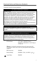
Electrical Safety and Emissions Standards This product meets the following standards. U.S. Federal Communications Commission Radiated Energy Note: This equipment has been tested and found to comply with the limits for a Class A digital device pursuant to Part 15 of FCC Rules. These limits are designed to provide reasonable protection against harmful interference when the equipment is operated in a commercial environment.
Translated Safety Statements Important: The indicates that a translation of the safety statement is available in a PDF document titled “Translated Safety Statements” (613-000990) posted on the Allied Telesis website at www.alliedtelesis.com. This document is also included with the documentation CD that is shipped with the product.
Contents Preface .............................................................................................................. 11 Safety Symbols Used in this Document .............................................................. 12 Where to Find Web-based Guides ...................................................................... 13 Contacting Allied Telesis ..................................................................................... 14 Online Support ..........................................
Contents Starting a Local Management Session ................................................................56 Removing the AT-MCF2000M Management Module...........................................59 Installing a Media Converter Module....................................................................61 Chapter 3: Troubleshooting .............................................................................63 Appendix A: Technical Specifications ............................................................
Figures Figure 1: AT-MCF2000M Management Module.................................................. 18 Figure 2: Front Panel of the AT-MCF2000M Management Module .................... 20 Figure 3: Example Stack of Four Media Converter Chassis ............................... 25 Figure 4: Maximum Stacking Cable Length ........................................................ 25 Figure 5: Pressing the Reset Button ................................................................... 30 Figure 6: Chassis ID Jumper..
Figures 8
Tables Table 1: Safety Symbols .................................................................................... 12 Table 2: General Status LEDs ............................................................................ 33 Table 3: Link/Activity LED on the RS-232 Terminal Port .................................... 34 Table 4: Link/Activity LED on the Management Port .......................................... 35 Table 5: Duplex-mode/Collisions LED on the Management Port .......................
Tables 10
Preface This guide contains the installation instructions for the AT-MCF2000M Management Module for the AT-MCF2000 Media Converter Series.
Preface Safety Symbols Used in this Document This document uses the safety symbols defined in Table 1. Table 1. Safety Symbols Symbol 12 Meaning Description Caution Performing or omitting a specific action may result in equipment damage or loss of data. Warning Performing or omitting a specific action may result in electrical shock.
AT-MCF2000M Management Module Installation Guide Where to Find Web-based Guides The installation and user guides for all Allied Telesis products are available in portable document format (PDF) from our web site at www.alliedtelesis.com. You can view the documents online or download them onto a local workstation or server.
Preface Contacting Allied Telesis This section provides Allied Telesis contact information for technical support as well as sales and corporate information. Online Support You can request technical support online by accessing the Allied Telesis Knowledge Base: www.alliedtelesis.com/ support. You can use the Knowledge Base to submit questions to our technical support staff and review answers to previously asked questions.
AT-MCF2000M Management Module Installation Guide If the FTP server prompts you to log on, enter “anonymous” as the user name and your email address as the password.
Preface 16
Chapter 1 Overview This chapter contains the following sections: “Features” on page 18 “Front Panel” on page 20 “10/100/1000Base-T Management Port” on page 21 “RS-232 Terminal Port” on page 23 “Stack Port” on page 24 “Reset Button” on page 29 “SD Slot” on page 31 “Chassis ID Jumper” on page 32 “Module LEDs” on page 33 17
Chapter 1: Overview Features The AT-MCF2000M unit is a management module for the media converter modules and chassis in the AT-MCF2000 Media Converter Series. With its preinstalled AT-S97 Management Software, this management device provides complete control over the operating parameters of the ports and channels on the AT-MCF2000 Media Converter Series.
AT-MCF2000M Management Module Installation Guide Here are some of the management functions you can perform with the module and the AT-S97 Management Software: Configure the operating parameters of the twisted pair ports in the media converter channels: – Auto-Negotiation – Speed – Duplex mode – MDI/MDI-X configuration Set the duplex mode of the fiber optic ports.
Chapter 1: Overview Front Panel Figure 2 illustrates the front panel of the AT-MCF2000M Management Module. AT-MCF2000M LINK ACT 1000 LINK ACT 10/100 LINK ACT FDX HDX COL PORT ACTIVITY STACK MANAGEMENT TERMINAL BOOT RESET RDY FAULT MASTER SD POWER 10/100/1000BASE-T RS-232 RDY BUSY 1199 Figure 2.
AT-MCF2000M Management Module Installation Guide 10/100/1000Base-T Management Port The 10/100/1000Base-T Management port is a standard Ethernet, Fast Ethernet, and Gigabit Ethernet port. The module communicates with your network through this port when it performs any of the management functions that require a network connection.
Chapter 1: Overview IEEE 802.3u compliant, the port can set its speed and duplex mode automatically with Auto-Negotiation, the default setting. Auto-Negotiation can be disabled and the speed and duplex mode set manually with the AT-S97 Management Software. The wiring configuration of the port is set automatically with auto-MDI/MDI-X to either MDI or MDI-X, depending on the wiring configuration of the end node.
AT-MCF2000M Management Module Installation Guide RS-232 Terminal Port The management module can be managed locally through this port with a console or a PC with a terminal emulation program. This type of management method is referred to as local or out-of-band management because it is not conducted over a network. The module comes with an RS-232 Serial Management cable for this type of management.
Chapter 1: Overview Stack Port You can simplify the management of two or more AT-MCF2000 chassis by interconnecting the devices with the Stack port and managing them as a single unit. Some of the benefits of the Stack port and the stacking feature are: A stack requires only one AT-MCF2000M Management Module. A stack can consist of up to eight AT-MCF2000 Multichannel Media Converter Chassis and 16 media converter modules. A stack requires only one IP configuration.
AT-MCF2000M Management Module Installation Guide An example of a stack with four media converter chassis is illustrated in Figure 3. Units with the AT-MCF2000S Stacking Module Unit with the AT-MCF2000M Management Module Figure 3. Example Stack of Four Media Converter Chassis The Stack port on the management module and the stacking module use standard straight-through or crossover TIA/EIA 568-B-compliant Enhanced Category 5 (Cat 5e) shielded or unshielded cabling with 100 ohm impedance.
Chapter 1: Overview A chassis with the AT-MCF2000S Stacking Module must be managed through the stack because the module does not have a port for a local connection. Note The traffic on the Stack ports on the AT-MCF2000M and AT-MCF2000S Modules is limited to management packets from the management and stacking modules. These ports do not carry media converter traffic. A media converter channel in a chassis of a stack operates as an independent entity.
AT-MCF2000M Management Module Installation Guide the management module is 0. The ID number for the AT-MCF2000S Stacking Module is set with DIP switches and can range from 1 to 30. The default value of the stacking module is 1. Before you install the management and stacking modules in a chassis, you must set the chassis ID numbers. The jumper and DIP switches are not accessible after the installation of the modules. In addition, the ID numbers cannot be controlled through the AT-S97 Management Software.
Chapter 1: Overview The chassis with the AT-MCF2000M Management Module must be at one end of the stack. The other units are connected to the stack with the AT-MCF2000S Stacking Module. Each chassis must be assigned a unique chassis ID number from 0 to 31. The ID number for the AT-MCF2000M Management Module can be 0 or 31. The range of the ID number for the AT-MCF2000S Stacking Module is from 1 to 30.
AT-MCF2000M Management Module Installation Guide Reset Button The Reset button on the front panel of the management module initializes the AT-S97 Management Software and the active master configuration file. Situations where resetting the module might be necessary include the following: To reconfigure the modules in the chassis or stack after selecting a new active master configuration file. For background information, refer to the AT-S85 and AT-S97 Management Software Command Line User’s Guide.
Chapter 1: Overview AT-M C F2000 M STAC K LINK MANA GEME ACT NT 1000 LINK TERM INAL ACT 10/100 LINK ACT PORT FDX ACTIV HDX ITY 10/100 RESE /1000B ASE-T T BOOT COL RDY FAULT RS-23 2 SD RDY BUSY AT-M CF2K FAN MAST ER POWE R STA TUS NO RM FAUL AL T 1203b Figure 5.
AT-MCF2000M Management Module Installation Guide SD Slot The SD slot accommodates a secure digital memory card. You might use a memory card in the following situations: Storing backup copies of the configuration files from the management and media converter modules - You can maintain a library of past configuration files in the event a module needs to be returned to a previous configuration.
Chapter 1: Overview Chassis ID Jumper The module has a jumper on the circuit board for setting the ID number of the module’s chassis. Refer to Figure 6. The chassis ID number for the AT-MCF2000M Management Module can be 0 or 31. The default setting is 0. For background information, refer to “Chassis ID Numbers” on page 26. For instructions on setting the jumper, refer to “Setting the Chassis ID Jumper” on page 45.
AT-MCF2000M Management Module Installation Guide Module LEDs The section describes the LEDs on the management module. General Status LEDs The three LEDs on the left side of the panel provide general information on the status of the management module. One LED is unlabeled. The other LEDs are Master and Power. INK ACT 1000 LINK ACT 10/100 LINK ACT FDX HDX COL PORT ACTIVITY EMENT TERMINAL BOOT RESET RDY FAULT MASTER SD POWER 0BASE-T RS-232 RDY BUSY 1199a General Status LEDs Figure 7.
Chapter 1: Overview Table 2. General Status LEDs (Continued) LED Master Power RS-232 Terminal Port LED State Description Off This state is designated for future use. Green The module is functioning as the master management module of the stack. Off The management module is not receiving power or the power is not within the permitted operating range. Green The management module is receiving power.
AT-MCF2000M Management Module Installation Guide 10/100/ 1000Base-T Management Port LEDs The 10/100/1000Base-T Management port has a L/A (Link/ Activity) LED and a D/C (Duplex-mode/Collisions) LED. AT-MCF2000M STACK LINK ACT MANAGEMENT 10/100/1000BASE-T 1000 LINK AC TERMINAL RS-232 1199b Link/Activity LED Duplex-mode/ Collisions LED Figure 9. Link/Activity and Duplex-mode LEDs on the Management Port The states of the Link/Activity LED are defined in Table 4. Table 4.
Chapter 1: Overview The states of the Duplex-mode/Collisions LED on the Management port are described in Table 5. Table 5. Duplex-mode/Collisions LED on the Management Port State Stack Port LED Description Steady Green The port is operating in full-duplex mode. Steady Amber The port is operating in half-duplex mode. Flashing Amber The port is operating in half-duplex mode with collisions. The L/A (Link/Activity) LED on the Stack port is shown in Figure 10.
AT-MCF2000M Management Module Installation Guide Table 6. Link/Activity LED on the Management Port State Description Flashing Green Secure Digital Memory Card Slot LED The port is forwarding or receiving management packets from the next chassis in the stack. The secure digital memory card slot has one LED. INK ACT 1000 LINK ACT 10/100 LINK ACT FDX HDX COL PORT ACTIVITY EMENT TERMINAL BOOT RESET RDY FAULT MASTER SD POWER 0BASE-T RS-232 RDY BUSY 1199a SD Slot LED Figure 11.
Chapter 1: Overview 38
Chapter 2 Installation This chapter contains the following sections: “Reviewing Safety Precautions” on page 40 “Cable Requirements” on page 42 “Unpacking the AT-MCF2000M Management Module” on page 44 “Setting the Chassis ID Jumper” on page 45 “Installing the Management Module” on page 47 “Cabling a Media Converter Stack” on page 52 “Verifying the Installation” on page 55 “Starting a Local Management Session” on page 56 “Removing the AT-MCF2000M Management Module” on page 59 “Installing
Chapter 2: Installation Reviewing Safety Precautions Please review the following safety precautions before you begin to install the management module. Note The indicates that a translation of the safety statement is available in a PDF document titled “Translated Safety Statements” (613-000990) posted on the Allied Telesis website at www.alliedtelesis.com. This document is also included with the documentation CD that is shipped with the product.
AT-MCF2000M Management Module Installation Guide Warning: Only trained and qualified personnel are allowed to install or to replace this equipment. E14 Caution: Do not install in direct sunlight, or a damp or dusty place. E16 Caution: Do not expose the device to moisture or water. E17 Warning: Mounting of the equipment in the rack should be such that a hazardous condition is not created due to uneven mechanical loading.
Chapter 2: Installation Cable Requirements 10/100/ 1000Base-T Management Port Table 8 lists the cable requirements for the 10/100/ 1000Base-T Management port. For background information, refer to “10/100/1000Base-T Management Port” on page 21. For port pinouts, refer to “10/100/ 1000Base-T Management Port Pinouts” on page 68. Table 8.
AT-MCF2000M Management Module Installation Guide Stack Port Table 9 lists the cable requirements for the Stack port. For background information, refer to “Stack Port” on page 24. Table 9. Cable Requirements for the Stack Port Cable Type Maximum Operating Distance Standard straight100 m (328 ft) through or crossover TIA/ EIA 568-B-compliant Enhanced Category 5 (Cat 5e) shielded or unshielded cabling with 100 ohm impedance.
Chapter 2: Installation Unpacking the AT-MCF2000M Management Module To unpack the module, perform the following procedure: 1. Remove all components from the shipping package. Note Store the packaging material in a safe location. You must use the original shipping material if you need to return the unit to Allied Telesis. 2. 44 Verify that the following items are included in the shipping package. If an item is missing or damaged, contact your Allied Telesis sales representative for assistance.
AT-MCF2000M Management Module Installation Guide Setting the Chassis ID Jumper The management module has a jumper on the circuit board for setting the chassis ID. The AT-MCF2000M Management Module can have a chassis ID value of 0, the default setting, or 31. You can leave the jumper in the default setting if the media converter chassis will not be part of a stack or for a stack that has just one management module.
Chapter 2: Installation Caution The management module is sensitive to and can be damaged by electrostatic discharge. Wear a grounding device and observe electrostatic discharge precautions when setting the chassis ID jumper. Note You cannot set the chassis ID number with the AT-S97 Management Software.
AT-MCF2000M Management Module Installation Guide Installing the Management Module Caution The management module is sensitive to and can be damaged by electrostatic discharge. Wear a grounding device and observe electrostatic discharge precautions when installing a management module in the chassis. Note The AT-MCF2000M Management Module supports hot swapping. You can install the module while the chassis is powered on. Note This procedure uses the AT-MCF2000 chassis for illustration purposes.
Chapter 2: Installation AT-M CF AT-M CF2K FAN 2KP NL3 STAT US NORM FAUL A T Figure 13. Removing the Blank Panel from the Management Slot 2. Remove the insulator labelled “REMOVE BEFORE INSTALL” from the battery on the management module by sliding it out from beneath the battery clip. Refer to Figure 14.
AT-MCF2000M Management Module Installation Guide 3. Align the edges of the module with the guides in the slot and carefully slide the module into the chassis until it is flush with the front of the chassis. Refer to Figure 15. Light pressure may be necessary to firmly seat the module connector on the connector on the back panel of the chassis. Caution Do not force the module into place. Doing so may damage the connector pins on the backplane of the chassis.
Chapter 2: Installation 4. Secure the management module to the chassis by tightening the two captive screws on the module with a cross-head screwdriver. Refer to Figure 16. AT-M CF20 00M STAC K LINK MANA GEME ACT 1000 LIN NT K TERM INAL ACT 10/100 LINK ACT PORT FDX ACTIV HDX ITY 10/100 RESE /1000B ASE-T T BOOT COL RDY FAULT RS-23 2 AT-M CF 2KFA N SD MAST ER POWE R RDY BUSY STA TUS NO RM FAUL AL T 1201a Figure 16. Securing the Management Module 5.
AT-MCF2000M Management Module Installation Guide 6. If the chassis will be part of a stack, Allied Telesis recommends affixing a label with the chassis ID number to the front of the unit. (Refer to “Setting the Chassis ID Jumper” on page 45 for information on the ID number.) The label should also include the chassis’ MAC address, found on the bottom panel of the device or displayed with the AT-S97 Management Software.
Chapter 2: Installation Cabling a Media Converter Stack To create a stack, connect the units together in a daisy chain topology using the Stack ports on the AT-MCF2000M and AT-MCF2000S modules. The Stack port on the AT-MCF2000M Management Module must be connected to the Stack 1 or Stack 2 port on the AT-MCF2000S Stacking Module in the next chassis of the stack. The remaining Stack port on the stacking module must be connected to either the Stack 1 or Stack 2 port in the next chassis, and so on.
AT-MCF2000M Management Module Installation Guide 2. To connect two AT-MCF2000S Stacking Modules, connect either the Stack 1 or Stack 2 port on the stacking module to either the Stack 1 or Stack 2 port on the stacking module in the next chassis of the stack. All port combinations are supported, as illustrated in Figure 19. Repeat this step to connect the remaining AT-MCF2000 media converter modules to the stack.
Chapter 2: Installation 3. 54 To connect the last chassis of a stack with just one management module, you can use either port on the AT-MCF2000S Stacking Module. The remaining port is left unused.
AT-MCF2000M Management Module Installation Guide Verifying the Installation This procedure verifies the installation of the AT-MCF2000M Management Module. The procedure assumes the chassis with the module is powered on. To verify the installation of the module, perform the following procedure: 1. Verify that the Power LED on the module is green. 2. If you connected a network cable to the 10/100/ 1000Base-T Management Module, verify that the L/A (Link/Activity) LED is green or amber. 3.
Chapter 2: Installation Starting a Local Management Session To start a local management session on the chassis or stack, perform the following procedure: 1. Connect the DIN-8 connector on the RS-232 Serial Management cable included with the AT-MCF2000M Management Module to the RS-232 Terminal port on the management module, as shown in Figure 20.
AT-MCF2000M Management Module Installation Guide Note The port settings are for a DEC VT100 or ANSI terminal, or an equivalent terminal emulator program. Note The prompt “Hit any key to stop autoboot,” displayed on the console when the management module is reset or power cycled, is for manufacturing purposes only and should be ignored. If you inadvertently display the manufacturing prompt (=>), type “bootapp” to launch the management software on the management module. 4. Press Enter.
Chapter 2: Installation chassis. For further information, refer to the AT-S85 and AT-S97 Management Software Command Line Interface User’s Guide.
AT-MCF2000M Management Module Installation Guide Removing the AT-MCF2000M Management Module The AT-MCF2000M Management Module supports hotswapping and can be removed from the unit when the chassis is powered on. However, the replacement of a management module may impact the operations of the media converter modules in the chassis. During normal operations, the media converter modules obtain their parameter settings from the master configuration file in the management module’s file system.
Chapter 2: Installation 4. If you are not replacing the module, reinstall the blank panel over the management slot. Note Do not leave a chassis slot open. An open slot allows dust to enter the chassis and reduces the airflow and cooling of the components. 5. If you are replacing the module, begin the installation of the new management module with “Unpacking the AT-MCF2000M Management Module” on page 44.
AT-MCF2000M Management Module Installation Guide Installing a Media Converter Module When a media converter module is installed into a chassis, the AT-S97 Management Software on the management module communicates with the module to determine the appropriate operating parameters for the device. Some of the variables that factor into the process include whether the chassis slot had been used by another media converter module and, if so, whether the new module is the same model as the previous module.
Chapter 2: Installation 62
Chapter 3 Troubleshooting This chapter contains suggestions on how to troubleshoot the AT-MCF2000M Management Module if a problem occurs. Problem 1: The Power LED on the module is off. Solutions: Try the following: Check the Status LED on the power supply module in the chassis. The LED should be steady green. If the LED is off or signalling a fault condition, refer to the chassis or power supply’s Installation Guide for troubleshooting instructions.
Chapter 3: Troubleshooting Problem 3: A network cable is connected to the 10/100/ 1000Base-T Management port, but the port’s Link/Activity LED is off. Solutions: Try the following: Verify the network device connected to the Management port is powered on and operating properly. Verify the twisted pair cable is securely connected to the port on the management module and on the remote network device. Verify you are using the correct type of cable for the port and have not exceeded the maximum length.
AT-MCF2000M Management Module Installation Guide Problem 5: A twisted pair cable is connected to the Stack port on the management module, but the port’s Link/Activity LED is off. Solutions: Try the following: Verify the next chassis in the stack is powered on and operating properly. Verify the twisted pair cable is securely connected to the Stack port on the management module and to the Stack port in the next chassis.
Chapter 3: Troubleshooting 66
Appendix A Technical Specifications Physical Specifications Dimensions (H x W x D) 3.1 x 9.7 x 20.8 cm (1.2 x 3.8 x 8.2 in.) Weight 340 g (0.75 lb.
Appendix A: Technical Specifications Safety and Electromagnetic Emissions Certifications EMI (Emissions): FCC Class A, EN55022 Class A, EN61000-3-2, EN61000-33, VCCI Class A, C-TICK, CE EMC (Immunity): EN55024 Electrical and Laser Safety: EN60950-1 (TUV), UL 60950-1 (CULUS), EN60825 Quality and Reliability: MTBF > 100,000 hrs. Compliance Marks: CE, CULUS, TUV, C-Tick 10/100/1000Base-T Management Port Pinouts This section lists the pinouts for the 10/100/1000Base-T Management port.
AT-MCF2000M Management Module Installation Guide Table 11 lists the pin signals when the management port is operating at 1000 Mbps. Table 11.
Appendix A: Technical Specifications RS-232 Terminal Port Pinouts Figure 23 illustrates the pin layouts for the DIN-8 connector and port of the RS-232 Terminal port. 7 6 8 6 7 3 8 4 1 5 2 3 5 4 158 2 1 Figure 23. RS-232 Terminal Port Pinouts Table 12 lists the pin signals for the RS-232 Terminal port. Table 12.