Enclosure and Intelligent Multiservice Gateways AT-iMG7x6MOD Electronics Unit Installation Guide
Copyright © 2009 Allied Telesis, Inc. All rights reserved. No part of this publication may be reproduced without prior written permission from Allied Telesis, Inc. Microsoft and Internet Explorer are registered trademarks of Microsoft Corporation. Netscape Navigator is a registered trademark of Netscape Communications Corporation. All other product names, company names, logos or other designations mentioned herein are trademarks or registered trademarks of their respective owners. Allied Telesis, Inc.
Contents Chapter 1: Preface ........................................................................................................................................... 5 Safety Symbols Used in this Document ................................................................................................................................................... 5 Reviewing Safety Precautions..............................................................................................................................
Contents Power Specifications...................................................................................................................................................................................48 Safety and Electromagnetic Emissions Certifications..........................................................................................................................48 Power Cord Wiring ..........................................................................................................
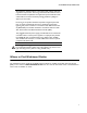
AT-iMG746MOD Gateway Installation Guide Chapter 1 Preface This guide contains instructions on how to install the AT-iMG7x6MOD series intelligent Multiservice Gateway. This guide has instructions for both outdoor and indoor installation. Note The iMG6x6MOD series intelligent Mulitservice Gateway, available before the iMG7x6MOD, supports the same software features and physical interfaces. Moreover, the installation procedures for the two product series are the same.
Preface Warning: To prevent electric shock, do not remove the cover. No user-serviceable parts inside. This unit contains hazardous voltages and should only be opened by a trained and qualified technician. To avoid the possibility of electric shock, disconnect electric power to the product before connecting or disconnecting the LAN cables. 3 Warning: Do not work on equipment or cables during periods of lightning activity. 4 Warning: Class I Equipment. This equipment must be earthed.
AT-iMG746MOD Gateway Installation Guide All installation methods shall be in accordance with national and local regulations and practices. The wiring method should include the use of Listed wire/cable acceptable for the application per the National Code, and should be one that an Authority Having Jurisdiction (AHJ) can approve per the Code.
Preface Contacting Allied Telesis This section provides Allied Telesis contact information for technical support as well as sales and corporate information. Online Support You can request technical support online by accessing the Allied Telesis Knowledge Base: http:// kb.alliedtelesis.com. You can use the Knowledge Base to submit questions to our technical support staff and review answers to previously asked questions.
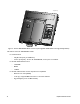
AT-iMG746MOD Installation Guide Chapter 2 Electronics Overview Features The AT-iMG746MOD is part of the iMG7x6MOD Series product. Figure 1. The AT-iMG746MOD Electronics Unit (with Gig BiDi WAN Module) Figure 2.
iMG7-angled-view-main.eps Figure 3. The AT-iMG746MOD Electronics Unit (with Gig BiDi WAN Module with Gig LAN RJ-45 Port) The features of the AT-iMG746MOD include: 10 Fixed Interfaces - 6 RJ-45 LAN ports (10/100 Base-T) - 4 Voice ports (FXS) - For the AT-iMG726MOD, 2 voice ports are available.
AT-iMG746MOD Installation Guide Module Combinations With the various modules that are available, the following table shows which module configurations are possible. Also, refer to “Understanding the LEDs (iMGMOD Unit)” on page 42. Table 2. Module Combinations for MOD Products Product iMG626 100M BiDi X EPON X iMG726 iMG646 iMG746 X X X X X X 1G BiDi X X 1G BiDi / Gig Lan X X HPNA (Low Band) X X X X T1/E1 X Xa X X(a) a.
Interfaces to the Network (Outdoor Versus Indoor Installation) The AT-iMG746MOD can be installed as part of an Outdoor or Indoor Installation. In an Outdoor Installation, the AT-EN746MOD Enclosure has already been installed, and the ATiMGxx6MOD Electronics unit is installed so that it fits inside the Enclosure. Follow these steps: 1. Refer to the AT-EN746MOD Enclosure Installation Guide for steps on how to install the Enclosure as well as figures that show the overall configuration. 2.
AT-iMG746MOD Installation Guide Example Configurations The following figures show one possible installation with the iMG746MOD. network-physical-indoor.ai ethernet (up to 6 ports) Upstream RJ11 (up to 4 ports) BD Fiber Coax (up to 8 ports) splitter Figure 4.
Chapter 2: Electronics Overview
AT-iMG746MOD Installation Guide Chapter 3 Installing the Gateway in the Enclosure This chapter describes how to install the gateway in the enclosure and assumes you have already installed the enclosure. Refer to the (Enclosure installation Guide) Required Tools and Supplies The following tools and supplies are required to install the gateway: Tools Have the following tools on hand before you install the enclosure or gateway: Flat head and #2 Phillips screwdrivers Wire cutters 5/32 in.
AT-iMG746MOD Installation Guide Note Store the packaging material in a safe location. You must use the original shipping material if you need to return the unit to Allied Telesis. AT-iMGxx6MOD chassis (LAN and WAN cards are already installed) This Installation Guide Accessory Kit that includes: – 2 #8-32 SEMS pan head Phillips screws – 6-pin DC terminal block Installing the Electronics Unit into the Enclosure Warning: This unit is intended for installation in a restricted access location.
AT-iMG746MOD Installation Guide 3. Use two of the #8-32 SEMS screws to secure the gateway to the grounding plate as shown in Figure 6. Figure 6. Mounting the Gateway Connecting Cables Cable Layout Overview Figure 7 shows the cable entrances. Note that the middle entrance is not used. Figure 7.
AT-iMG746MOD Installation Guide Connecting the Fiber Pigtail Connect the pigtail (installed as part of the Enclosure installation procedure) to the WAN fiber port of the electronics unit. Refer to Figure 8. Connecting the Power Cord The AT-iMGxx6MOD gateway is designed to be deployed with an uninterrupted power supply (UPS). You can purchase a UPS from Allied Telesis (part number AT-iMG008/AT-iMG008G). Install the power supply according to the manufacturer’s instructions included in the package.
AT-iMG746MOD Installation Guide Connecting the Coax to the Home Network (if applicable) With the HPNA card, the AT-iMG746MOD allows PCs, Set Top Boxes, VCRs, etc. to become members of an ethernet subnet over the coax network that is already installed. Figure 9 shows an example. The coax-toethernet converter can be purchased as ATI Part Number AT-iMG007.
AT-iMG746MOD Installation Guide Warning If the iMG is going to be used to provide HPNA over coax services to the home, the installer must verify the home coax network has been properly grounded per the NEC/Local codes. If the installer is unable to verify the coax is properly grounded, the iMG must be directly connected to building primary ground.
AT-iMG746MOD Installation Guide Connecting the T1/E1 Cable (if applicable) With the DS/T1 card, DS/E1 equipment can be connected over the network. (For connection to the DS/E1 network from the iMAP, a CES8 card would be used.) Refer to Figure 11. Customer Central Office/POP DS1/E1 supports: SF, ESF, SLC96, D4, AMI, B8ZS CES8 Fiber (FX, EPON, etc) WAN Input T1 T1 iMAP configured with CES8 PBX or other DS1/E1 equipment iMG-T1-functional PBX or other DS1/E1 equipment Figure 11.
AT-iMG746MOD Installation Guide Connecting the 1G LAN (RJ-45) - if applicable With the WAN-GIG-BD-LN module, both the WAN and LAN ports can be configured, since the LAN side is an RJ-45 that is configured directly on the module. Refer to the following figure. Note Activating the copper Gigabit LAN interface disables the interface to the T1/E LAN module, and so the T1/E LAN module cannot be used.
AT-iMG746MOD Installation Guide Connecting the Telephone Wires To connect the telephone wires, perform the following procedure: 1. Remove the grommet from the telephone wire/ LAN entrance. 2. Connect the telephone wires to each pair of telephone terminal posts in the enclosure, as well as the appropriate RJ-11 connectors, as shown in Figure 14, at 5.3 in-lbs. Figure 14. Connecting the Telephone Wires 3. Perform the next steps based on the following: a.
AT-iMG746MOD Installation Guide Connecting the LAN Cables To connect the LAN cables, perform the following procedure: 1. Remove the grommet from the LAN cable entrance. (This step has already been done if you have installed the phone cable.) Note Allied Telesis recommends that you fully wire all six ports to allow for easy service expansion in the future. 2. Insert a UV-rated wire tie through the slots at the bottom of the entrance. 3. Connect the LAN cables to the RJ-45 ports on the gateway. 4.
AT-iMG746MOD Installation Guide Prepare for Initial Startup To complete the installation, perform the following procedure: 1. Install an uninterruptible power supply according to the manufacturer’s instructions. 2. If necessary, plug the management cable into the console port. For networks with remote management enabled, no local configuration is required. 3. The physical installation is now complete, as shown in Figure 16. Figure 16.
AT-iMG746MOD Installation Guide 26 Chapter 3: Installing the Gateway in the Enclosure
Chapter 4 Installing the Gateway Indoors This chapter describes how to install the gateway in an indoor location. Warning This unit is intended for installation in a restricted access location. A restricted access location in where access can only be gained by authorized service personnel through the use of a special tool, lock and key, or other means of security, and is controlled by the authority responsible for that location.
AT-iMG646MOD Installation Guide Preparing for the Installation To prepare for the installation, perform the following procedure: 1. Remove all components from the shipping package. Note Store the packaging material in a safe location. You must use the original shipping material if you need to return the unit to Allied Telesis. 2. Ensure that the following components are included in the gateway package. If any item is missing or damaged, contact your Allied Telesis sales representative for assistance.
AT-iMG646MOD Installation Guide Mount the Grounding Stud 1. Put the included #8-32 x 0.5 in. SEMS screw through the right chassis grounding hole in the chassis, as shown in Figure 17 2. Secure the screw with a #8-32 Kepnut (not provided), as shown in Figure 17. Figure 17. Mounting the Grounding Assembly on the Right Mounting Hole (Note: Instead of the #8-32 Kepnut, you can also use a #8 nut with a lock washer.
AT-iMG646MOD Installation Guide 5. Fasten the plywood to the wall, using the holes that you drilled in Step 4. Use screws that ensure the plywood can withstand a downward force of 20 pounds. Refer to Figure 18. Figure 18. Securing the Plywood to the Wall Attach Wall Mounting Bracket and Mark Mounting Holes 1. Take the wall mounting bracket and attach it to the top of the gateway using the three remaining mounting screws, as shown in Figure 19 Figure 19.
AT-iMG646MOD Installation Guide Mount the Gateway to the Mounting Surface 1. Secure the gateway to the mounting surface with at least three wood screws (not included), starting with the upper right corner, as shown in Figure 20. Note Ensure the bracket can withstand 20 pounds of downward pressure. Figure 20.
AT-iMG646MOD Installation Guide Connecting the Ground Wire To connect the ground wire, perform the following procedure: 1. Prepare an adequate length of 14AWG stranded grounding wire for the ground connection. 2. Strip 0.25 in.(0.7 cm) of insulation from the ground wire and crimp it into the ground wire ring lug. 3. Secure the ring lug on the stud with a washer and #8-32 Kepnut, as shown in Figure 21. Figure 21. Securing the Ground Wire Lug 4.
AT-iMG646MOD Installation Guide Connecting the Power Cord The AT-iMGxx6MOD gateways are designed to be deployed with an uninterrupted power supply (UPS). You can purchase a UPS from Allied Telesis (part number AT-iMG008/AT-iMG008G). Install the power supply according to the manufacturer’s instructions included in the package. Allied Telesis provides a 15 ft. power cable (part number AT-iMG646MOD-C01). Alternatively, you can make custom length power cables.
AT-iMG646MOD Installation Guide Connecting the Fiber Optic Cable (BD and EPON) To connect the fiber optic cable, perform the following procedure: 1. Remove the dust plug from the fiber optic port on the gateway and clean the port and connector. (See Appendix B, “Cleaning Fiber Optic Connectors” on page 51 for information.) 2. Connect the pigtail cable to the fiber optic port on the gateway, as shown in Figure 23 . Figure 23.
AT-iMG646MOD Installation Guide Connecting the Coax Cable (if applicable) With the HPNA card, the AT-iMGxx6MOD allows PCs, Set Top Boxes, VCRs, etc. to become members of an ethernet subnet over the coax network that is already installed. Figure 24 shows an example. The coax-toethernet converter can be purchased as ATI Part Number AT-iMG007.
AT-iMG646MOD Installation Guide Connecting the T1/E1 Cable (if applicable) With the DS/T1 card, DS/E1 equipment can be connected over the network. (For connection to the DS/E1 network from the iMAP, a CES8 card would be used.) Refer to Figure 26. Customer Central Office/POP DS1/E1 supports: SF, ESF, SLC96, D4, AMI, B8ZS CES8 Fiber (FX, EPON, etc) WAN Input T1 T1 iMAP configured with CES8 PBX or other DS1/E1 equipment iMG-T1-functional PBX or other DS1/E1 equipment Figure 26.
AT-iMG646MOD Installation Guide Connecting the 1G LAN (RJ-45) - if applicable With the WAN-GIG-BD-LN module, both the WAN and LAN ports can be configured, since the LAN side is an RJ-45 that is configured directly on the module. Refer to the following figure. Note Activating the copper Gigabit LAN interface disables the interface to the T1/E1 LAN module, and so the T1/E1 LAN module cannot be used.
AT-iMG646MOD Installation Guide Connecting the Telephone Wires To connect the telephone wires, simply connect each phone line directly into the RJ-11 ports on the ATiMGxx6MOD. Connecting the LAN Cables To connect the LAN cables, perform the following procedure: Note Allied Telesis recommends that you fully wire all six ports to allow for easy service expansion in the future. 1. Connect the LAN cables to the RJ-45 ports on the gateway, as shown in Figure 29 . Figure 29.
AT-iMG646MOD Installation Guide Prepare for Initial Startup To complete the installation, perform the following procedure: 1. Install an uninterrupted power supply according to the manufacturer’s instructions. 2. Plug the management cable into the console port. 3. The physical installation is now complete.
AT-iMG646MOD Installation Guide 40 Chapter 4: Installing the Gateway Indoors
AT-iMG746MOD Installation Guide Chapter 5 Turn-Up and Troubleshooting Turn-up Sequence The AT-iMG7x6MOD is shipped with main software image and a recovery software image, which is used when the main image is corrupted during download. These files are used during turn-up or may be replaced, depending on the DHCP provisioning sequence. Since the initial provisioning of the AT-iMG7x6MOD is done using DHCP, the user must ensure that the DHCP configuration has been set up correctly.
AT-iMG746MOD Installation Guide Understanding the LEDs (iMGMOD Unit) Figure 30. LEDs for AT-iMG7x6MOD Table 3. LEDs and Meanings LED Meanings PWR ON - The iMG is receiving power and the voltage is within the acceptable range. OFF - The unit is not receiving power. SYST ON - The unit is starting up or is malfunctioning OFF - The unit is working normally.
AT-iMG746MOD Installation Guide Table 3. LEDs and Meanings (Continued) RJ-45 LED Left - Link - ON - A LAN link has been established - OFF -A LAN link has not been established Right - Ethernet Activity - ON - A connection has been established - OFF -A connection has not been established - Flashing - The link is active Troubleshooting This chapter contains information on how to troubleshoot the gateway in the event that a problem occurs. Problem: Gateway is not operating correctly.
AT-iMG746MOD Installation Guide Problem: The VOIP LED remains off when you lift up the receiver on the connected telephone. Solution 1: Verify that the telephone cable is correctly connected, that the correct cable is being used, and that the cable is not damaged. Solution 2: Unplug the RJ-11 pigtail for the telephone circuit in question. Plug a POTS telephone into the RJ11 jack. If the VOIP LED lights up when you lift the receiver, then there may be a problem with the telephone cable.
AT-iMG746MOD Installation Guide Understanding the LEDs (T1/E1 Card) NETWORK LINK ADMIN 2 1 NETWORK LINK ADMIN T1_DS1_LEDs.ai Figure 31. LEDs for AT-iMG7x6MOD - T1/E1 Card Table 4. LEDs and Meanings - for each port No. LED ADMIN LEDLINK LED NETWORK Meanings 1 ON Off Off Port enabled, no errors (no faults) 2 ON ON Off Port enabled, but in a failed state (e.g. LOS) 3 ON Off ON The PSPAN has failed. 4 Blink@ .5Hz Blink@ .
AT-iMG746MOD Installation Guide 46 Chapter 5: Turn-Up and Troubleshooting
AT-iMG646MOD Installation Guide Appendix A Technical Specifications Orderable Parts Go to www.alliedtelesis.com, along the top menu banner select Products, along the side menu select CPE Gateways, and then RESIDENTIAL GATEWAYS. The tabs include supporting documentation. Physical Specifications (iMG746MOD) Dimensions: Weight: AT-EN646MOD 330 mm x 230.7 mm x 43.2 mm (13 in x 9.1 in x 1.7 in) AT-iMG746MOD 222 mm x 222 mm x 25 mm (8.75 in x 8.75 in x 1.0 in) AT-EN746MOD 1.
Appendix A: Technical Specifications Environmental Specifications Operating Temperature:-40° C to 65° C (-40° F to 150° F) Storage Temperature:-40° C to 70° C (-4° F to 158° F) Operating Humidity:5% to 90% non-condensing Storage Humidity: 5% to 95% non-condensing Operating Altitude Range:Up to 3,000 m (9,843 ft) Power Specifications Input Supply Voltage:12 V DC Power Consumption:10W typical, 18W max Safety and Electromagnetic Emissions Certifications 48 EMI/RFI: FCC Class B, EN55022 Class B, VCCI Clas
AT-iMG646MOD Installation Guide Power Cord Wiring To wire the terminal block for the gateway to the terminal block for the power supply cord, refer to Figure 32 and Table 5. iMG Terminal Block Power Supply Terminal Block Figure 32. Gateway Terminal Block to Power Cord Terminal Block Wiring Diagram Table 5.
Appendix A: Technical Specifications Serial Port Wiring The CONSOLE port is an RJ45 connection (not a DB9 connection used with other Allied Telesis products). Pinout is as follows. Note When looking at the RJ-45 port, pin 1 is on the right.
Appendix B Cleaning Fiber Optic Connectors The fiber optic connector consists of a fiber optic plug and its adapter. The end of the fiber optic cable is held in the core of the ferrule in the plug. Light signals are transmitted through the core of the fiber. Even minor smudges or dirt on the end face of the fiber, completely invisible to the naked eye, can disrupt light transmission and lead to failure of the component or of the entire system.
Appendix B: Cleaning Fiber Optic Connectors Using a Cartridge-Type Cleaner Fiber optic cartridge cleaners are available from many vendors and are typically called “cartridge cleaners,” as shown in Figure 35. Figure 35. Cartridge Cleaner Note Do not use compressed air or aerosol air to clean a fiber optic connector. To clean a fiber optic connector using a cartridge cleaner, perform the following procedure. 7.
AT-iMG646MOD Installation Guide Note Rub the ferrule tip on the cleaning surface in one direction only. 9. When you reach the end of the cleaning surface, pick up the ferrule tip, rotate and place it at the top and rub downwards at least 2 times. Caution Failing to pick up the ferrule tip when you reach the bottom of the cleaning surface can result in static electricity that can damage the fiber optic cable. 10. If desired, repeat steps 3 and 4. 11.
Appendix B: Cleaning Fiber Optic Connectors Using a Swab Specially treated swabs (stick cleaners) are available for cleaning inside connector adapters or hard-to-reach ferrule tips. These swabs, often referred to as “lint free” or “alcohol free” swabs, are available from many vendors, as shown in Figure 37. Stick cleaners are available in both 2.5 mm and 1.25 mm sizes for use on SC and MU connectors respectively. Note NEVER use a household cotton swab and/or alcohol to clean a fiber optic connector.
AT-iMG646MOD Installation Guide 2. If desired, repeat step 1. 3. If a fiber inspection scope is available, use the scope to inspect the connector to make sure that it is clean and to check for scratches, pits, or other problems that may affect performance. Note Always keep a dust cap on a fiber optic cable when it is not in use. Note Do not touch the end face of the ferrule in the connector. Warning: Do not stare into the laser beam.