
Installation guide


Installation
8
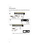
6. Attach the data cables and observe normal operation as indicated by the port
LEDs. Use only one Port 8, either Port 8 MDI or Port 8 MDI-X. For typical
configuration information, refer to “Cascade Configuration” on page 9.
7. Attach fiber optic cable with SC connectors to Port 9 and observe LEDs for
normal operation.
Note
Auto-negotiation for transmission mode supports full-duplex only if the
connected device also negotiates for full-duplex transmission mode. Port 9
supports full-duplex operation only.
You are finished with rackmount installation.
Standalone Configuration
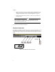
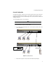
In a standalone configuration, the switch supports up to 9 network nodes. Figure 3 shows a
switch connected to end stations and a server. The basic physical connection for this
configuration requires connecting one of the switch’s ports to the adapter card of an end
station.
Figure 3
AT-FS709FC Connected to End Stations
TX RX
Copper
Fiber
Full-Duplex