
Installation guide


Chapter 4: Installing the Power Supplies
92
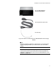
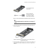
4. Check the model name, shown in Figure 49, to verify the module.
If the module is the AT-SBxPWRSYS1 System Power Supply, do not
continue with this procedure. Instead, perform “Installing the AT-
SBxPWRSYS1 System Power Supply” on page 83.
Figure 49. Verifying the AT-SBxPWRPOE1 PoE Power Supply
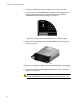
5. Raise the locking handle on the AT-SBxPWRPOE1 Power Supply, as
shown Figure 50.
Figure 50. Unlocking the Handle on the AT-SBxPWRPOE1 Power Supply
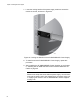
6. Align and insert the AT-SBxPWRPOE1 Module into slot A or B. See
Figure 51 on page 93.
Caution
The AT-SBxPWRPOE1 Power Supply will not work in slot C or D.