AT-A65 Expansion Module Installation and Safety Guide 3 V X - X4 0 RE EV 11-0 -00 R -00-6 611 843 44-000 8 BRO BCM AD C CO 8823G0829 546 1S M A2K P 82 QM 1A??11 G
AT-A65 Expansion Module AT-A65 Expansion Module Installation and Safety Guide Document Number 613-001135 Rev A. Copyright © 2008 Allied Telesis Inc. All rights reserved. No part of this publication may be reproduced without prior written permission from Allied Telesis, Inc. Allied Telesis, Inc. reserves the right to make changes in specifications and other information contained in this document without prior written notice. The information provided herein is subject to change without notice.
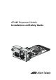
Installation and Safety Guide 3 Package Contents The following items are included with each AT-A65 expansion module. Contact your authorised Allied Telesis distributor or reseller if any items are damaged or missing. ■ One AT-A65 expansion module ■ One AT-A65 Expansion Module Installation and Safety Guide ■ One warranty card Compatible Switches Caution Attempting to install a module into a switch which is not compatible may damage the switch and the module.
AT-A65 Expansion Module 10/100/1000Base-T copper port qualities The port has the following qualities: ■ 10, 100, and 1000Mbps auto-sensing ■ half duplex and full duplex auto-negotiation at 10/100Mbps ■ full duplex auto-negotiation at 1000Mbps ■ auto-MDI / MDI-X For 10Base-T you can use Category 3 cables or better. For 100/1000Base-T you can use Category 5 cables or better. The maximum cable length is 100 m (328 ft).
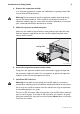
Installation and Safety Guide 5 4. Prepare the expansion module. In an antistatic environment, remove the module from its packing material. Be sure to observe ESD precautions. Warning Do not attempt to install an expansion module without observing correct antistatic procedures. Failure to do so may damage the switch or expansion module. If you are unsure what the correct procedures are, contact your authorised Allied Telesis distributor or reseller. 5. Slide the expansion module into place.
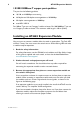
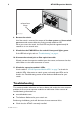
AT-A65 Expansion Module release lever hinge module_sfp.eps 8. Restart the switch. Until the switch is restarted, the output of the show system and show switch port commands cannot reflect the newly inserted module or SFP. When you restart the switch, the Fault LED may flash for approximately 10 seconds as it runs internal tests. 9. Check that the PWR LED on the switch’s front panel lights green. If the LED fails to light, refer to “Troubleshooting” on page 6. 10.
Installation and Safety Guide 7 ■ Make sure the power cord is securely connected to the switch and power outlet. ■ Check that the power supply voltage to the switch is stable. ■ Check that the correct data cables are being used and that their connections are secure. ■ Make sure that other network devices are working properly. ■ Use the show install command to check that the latest software version is loaded.
AT-A65 Expansion Module Regulatory Standards U.S. Federal Communications Commission RADIATED ENERGY Note: This equipment has been tested and found to comply with the limits for a Class A digital device pursuant to Part 15 of the FCC Rules. These limits are designed to provide reasonable protection against harmful interference when the equipment is operated in a commercial environment.