
Installation guide


Troubleshooting
68
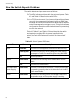
How the Switch Reports Problems
The switch detects and processes errors as follows:
# The LEDs indicate problems with the ports and power. Table
4-1 and Table 4-2 describe the switch LEDs.
# In a TCP/IP environment, if you have configured the software
correctly, the management software triggers an SNMP trap
message. As a result, the software then sends traps to alert the
network manager when a trigger occurs. This type of software
configuration allows the network administrator to proactively
monitor the network.
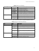
Table 4-1, Table 4-2, and Table 4-3 list and describe the switch
and expansion module LEDs. As power is applied to the
switch, the Fault LED flashes as the switch runs internal self
tests.
Table 4-1 Switch System LED Status
LED State Description
Fault Solid Red The switch or management software is malfunctioning.
Flashing Red The switch is booting, running diagnostic tests, writing
messages to FLASH, or transferring files using XMODEM.
Off Normal operation.
Master Solid Amber The switch is functioning as the master switch for the
stack.
OFF The switch is a slave switch.
RPS (Redundant
Power Supply)
Solid Green The RPS is connected to the switch. To verify that the RPS
is operating correctly, refer to the instructions in the RPS
Quick Install Guide.
Power Solid Green The switch is receiving power, the voltage is within the
acceptable range, and the power supply is working.