
Installation guide


Hardware Description
16
Switch LEDs
The Ethernet switch has a series of LEDs for monitoring the status of
the unit. There are system LEDs for monitoring the entire switch and
port LEDs for monitoring the individual data ports.
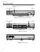
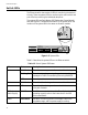
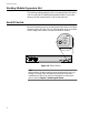
The system LEDs are Fault, Master, RPS (Redundant Power Supply),
and PWR. Figure 1-5 illustrates the location of the system LEDs. The
location of the system LEDs is the same on all switch models.
Figure 1-5 System LEDs
Table 1-2 describes the system LEDs on the Ethernet switch.
STATUS
RESET
FAULT
MASTER
RPS
PWR
10BASE-T / 100BASE-TX
FAST ETHERNET SWITCH
1
2
3
4
5
6
7
8
9
10
11
12
13
14
15
16
17
18
19
20
21
22
23
24
10BASE-T / 100BASE-TX
1X 3X 5X 7X
2X 4X 6X 8X
9X 11X 13X 15X
10X 12X 14X 16X
17X 19X 21X 23X
18X 20X 22X 24X
A
B
RS-232
TERMINAL PORT
100M LINK / ACTIVITY 10M LINK / ACTIVITY
HALF DUP/
COL
FULL DUP
PORT ACTIVITY
L/A
L/A
D/C
D/C
L/A
D/C
STATUS
RESET
FAULT
MASTER
RPS
PWR
RS-232
MINAL PORT
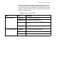
Table 1-2 Switch System LED Status
LED State Description
Fault Solid Red The switch or management software is malfunctioning.
Flashing Red The switch is booting, running diagnostic tests, writing
messages to FLASH, or transferring files using XMODEM.
OFF Normal operation.
Master Solid Amber The switch is functioning as the master switch of the stack.
Off The switch is functioning as a slave switch in the stack or is
not a part of a stack.
RPS (Redundant
Power Supply)
Solid Green The RPS is connected to the switch. To verify that the RPS is
operating correctly, refer to the instructions in the RPS
Quick Install Guide.
Power Solid Green The switch is receiving power, the voltage is within the
acceptable range, and the power supply is working.