AT-9400 Series Gigabit Ethernet Switches Layer 2+ Basic Layer 3 ◆ Installation Guide 613-001273 Rev.
Copyright © 2009 Allied Telesis, Inc. All rights reserved. No part of this publication may be reproduced without prior written permission from Allied Telesis, Inc. Allied Telesis and the Allied Telesis logo are trademarks of Allied Telesis, Incorporated. All other product names, company names, logos or other designations mentioned herein are trademarks or registered trademarks of their respective owners. Allied Telesis, Inc.
Electrical Safety and Emissions Standards This product meets the following standards. U.S. Federal Communications Commission Radiated Energy Note: This equipment has been tested and found to comply with the limits for a Class A digital device pursuant to Part 15 of FCC Rules. These limits are designed to provide reasonable protection against harmful interference when the equipment is operated in a commercial environment.
Translated Safety Statements Important: The indicates that a translation of the safety statement is available in a PDF document titled “Translated Safety Statements” (613-000990) posted on the Allied Telesis website at www.alliedtelesis.com. This document is also included with the documentation CD that is shipped with the product.
Contents Preface ..................................................................................................................................................................................7 Product Documentation8 Where to Go First ...................................................................................................................................................................9 Starting a Management Session .............................................................................
Contents Implementation ..............................................................................................................................................................40 AT-RPS3204 Redundant Power Supply ...............................................................................................................................41 AC Power Connector ................................................................................................................................................
Preface This guide contains the installation instructions for the AT-9400 Layer 2+ and Basic Layer 3 Gigabit Ethernet Switches.
Preface Product Documentation For overview information on the features of the AT-9400 Switches and the AT-S63 Management Software, refer to: AT-S63 Management Software Features Guide (PN 613-001022) For instructions on how to start local or remote management sessions on stand-alone AT-9400 Switches or AT-9400Ts Stacks, refer to: Starting an AT-S63 Management Session Guide (PN 613-001023) For instructions on how to install or manage stand-alone AT-9400 Switches, refer to: AT-9400 Gigabit Ethernet
AT-9400 Series Gigabit Ethernet Switches Installation Guide Where to Go First Allied Telesis recommends that you read Chapter 1, “Overview,” in the AT-S63 Management Software Features Guide before you begin to manage the switch for the first time. There you will find a variety of basic information about the unit and the management software, like the two levels of manager access levels and the different types of management sessions.
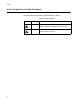
Preface Safety Symbols Used in this Document This document uses the safety symbols defined in Table 1. Table 1. Safety Symbols Symbol 10 Meaning Description Caution Performing or omitting a specific action may result in equipment damage or loss of data. Warning Performing or omitting a specific action may result in electrical shock.
AT-9400 Series Gigabit Ethernet Switches Installation Guide Contacting Allied Telesis This section provides Allied Telesis contact information for technical support and for sales and corporate information. Online Support You can request technical support online by accessing the Allied Telesis Knowledge Base: www.alliedtelesis.com/support/kb.aspx. You can use the Knowledge Base to submit questions to our technical support staff and review answers to previously asked questions.
Preface 12
Chapter 1 Overview The AT-9400 Switches are managed Gigabit Ethernet switches for Ethernet, Fast Ethernet, and Gigabit Ethernet networks. The AT-9400 Switches are divided into two groups: Layer 2+ Switches – AT-9408LC/SP – AT-9424T/GB – AT-9424T/SP Basic Layer 3 Switches – AT-9424T – AT-9424T/POE – AT-9424Ts – AT-9424Ts/XP – AT-9448T/SP – AT-9448Ts/XP The differences between the two groups are explained in the AT-S63 Management Software Features Guide.
Chapter 1: Overview 14 “Power Over Ethernet” on page 39 “AT-RPS3204 Redundant Power Supply” on page 41 “AC Power Connector” on page 42
AT-9400 Series Gigabit Ethernet Switches Installation Guide Descriptions The following sections describe the AT-9400 Switches.
Chapter 1: Overview AT-9424T/GB Switch The AT-9424T/GB Layer 2+ Switch has the following hardware features: 24 10/100/1000Base-T ports Two gigabit interface connector (GBIC) transceiver slots An RJ-45 style serial terminal port for local (out-of-band) management Status LEDs for the ports, transceiver slots, and system Redundant power supply connector Figure 2 shows the front and back panels of the AT-9424T/GB Switch.
AT-9400 Series Gigabit Ethernet Switches Installation Guide AT-9424T/SP Switch The hardware features of the AT-9424T/SP Layer 2+ Switch include: 24 10/100/1000Base-T ports Two Gigabit Ethernet small form-factor pluggable (SFP) transceiver slots An RJ-45 style serial terminal port for local (out-of-band) management Status LEDs for the ports, transceiver slots, and system Redundant power supply connector Figure 3 shows the front and back panels of the AT-9424T/SP Switch.
Chapter 1: Overview AT-9424T Switch The AT-9424T Basic Layer 3 Switch has these hardware features: 24 10/100/1000Base-T ports Four Gigabit Ethernet small form-factor pluggable (SFP) transceiver slots An RJ-45 style serial terminal port for local (out-of-band) management Status LEDs for the ports, transceiver slots, and system Figure 6 shows the front and back panels of the AT-9424T Switch.
AT-9400 Series Gigabit Ethernet Switches Installation Guide AT-9424T/POE Switch The AT-9424T/POE Basic Layer 3 Switch has these hardware features: 24 10/100/1000Base-T ports with Power over Ethernet (PoE) Four Gigabit Ethernet small form-factor pluggable (SFP) transceiver slots An RJ-45 style serial terminal port for local (out-of-band) management Status LEDs for the ports, transceiver slots, and system Figure 5 shows the front and back panels of the AT-9424T/POE Switch 1 3 5 7 9 11
Chapter 1: Overview AT-9424Ts Switch The AT-9424Ts Basic Layer 3 Switch has these hardware features: 24 10/100/1000Base-T ports Four Gigabit Ethernet small form-factor pluggable (SFP) transceiver slots An RJ-45 style serial terminal port for local (out-of-band) management Status LEDs for the ports, transceiver slots, and system Redundant power supply connector Compact flash card slot Expansion slot for the AT-StackXG Stacking Module Figure 6 shows the front and back panels of t
AT-9400 Series Gigabit Ethernet Switches Installation Guide AT-9424Ts/XP Switch The AT-9424Ts/XP Basic Layer 3 Switch has these hardware features: 24 10/100/1000Base-T ports Four Gigabit Ethernet small form-factor pluggable (SFP) transceiver slots Two 10 Gigabit Ethernet small form factor pluggable (XFP) transceiver slots An RJ-45 style serial terminal port for local (out-of-band) management Status LEDs for the ports, transceiver slots, and system Redundant power supply connector
Chapter 1: Overview AT-9448T/SP Switch The hardware features of the AT-9448T/SP Basic Layer 3 Switch include: 48 10/100/1000Base-T ports Four Gigabit Ethernet SFP transceiver slots An RJ-45 style serial terminal port for local (out-of-band) management. Status LEDs for the ports, transceiver slots, and system Redundant power supply (RPS) connector Compact flash card slot Figure 8 shows the front and back panels of the AT-9448T/SP Switch.
AT-9400 Series Gigabit Ethernet Switches Installation Guide AT-9448Ts/XP Switch The AT-9448Ts/XP Basic Layer 3 Switch has the following hardware features: 48 10/100/1000Base-T ports Two 10 Gigabit Ethernet small form factor pluggable (XFP) transceiver slots An RJ-45 style serial terminal port for local (out-of-band) management Status LEDs for the ports, transceiver slots, and system Redundant power supply connector Compact flash card slot Expansion slot for the AT-StackXG Stacki
Chapter 1: Overview 10/100/1000Base-T Twisted Pair Ports This section describes the twisted pair ports on the switches. (This section does not apply to the AT-9408LC/SP Switch.) Connector Type Speed The ports are 8-pin RJ-45 connectors that use four pins at 10 or 100 Mbps and all eight pins at 1000 Mbps. For the pin assignments, refer to “RJ-45 Twisted Pair Port Pinouts” on page 78. A port’s speed can be 10, 100, or 1000 Mbps.
AT-9400 Series Gigabit Ethernet Switches Installation Guide Maximum Distance Cable Type Auto-MDI/ MDI-X The ports have a maximum operating distance of 100 meters (328 feet). The cabling requirements for a 10/100/1000Base-T port are: For 10 Mbps operation: Standard TIA/EIA 568-B-compliant Category 3 or better shielded or unshielded cabling with 100 ohm impedance and a frequency of 16 MHz.
Chapter 1: Overview Fiber Optic Ports This section applies to ports 1 through 8 on the AT-9408LC/SP Switch. Connector Type Speed Maximum Distance and Cabling The ports feature LC-duplex connectors. The ports have fixed speed of 1000 Mbps (1000Base-SX). The ports have a maximum distance of 275 meters (m) with 62.5/125 µm (core/cladding) multimode fiber optic cable and 550m with 50/125 µm multimode fiber optic cable.
AT-9400 Series Gigabit Ethernet Switches Installation Guide GBIC Transceiver Slots For interconnecting devices over large distances using fiber optic cable, the AT-9424T/GB Switch has two slots on the front panel labeled 23 and 24 for optional fiber optic Gigabit Interface Converter (GBIC) Ethernet transceivers. Figure 10 illustrates a GBIC transceiver. Figure 10 GBIC Transceiver GBIC transceiver slots 23 and 24 are paired with twisted pair ports 23R and 24R.
Chapter 1: Overview SFP Transceiver Slots Several of the AT-9400 Switches feature slots for optional Gigabit Ethernet SFP transceivers for interconnecting network devices over large distances using fiber optic cable. With the exception of the AT-9408LC/SP Switch, each SFP slot is paired with a twisted pair port. A link on an SFP transceiver takes priority in the event both an SFP transceiver and its paired twisted pair port have established links to their respective end nodes.
AT-9400 Series Gigabit Ethernet Switches Installation Guide XFP Transceiver Slots Several AT-9400 Switches have slots for optional XFP 10 Gigabit Ethernet transceivers to connect high speed, 10 gigabit devices to the switch or create high speed backbone networks between switches. Figure 12 shows an example of an XFP transceiver. 721 Figure 12 XFP Transceiver Note For a list of supported XFP transceivers, contact your Allied Telesis sales representative.
Chapter 1: Overview Redundant Twisted Pair Ports Some AT-9400 Switches have two or four twisted pair ports that are paired with GBIC or SFP slots. The twisted pair ports are identified with the letter “R” for “Redundant” as part of their number on the front faceplate of the unit. The ports and slots are listed in Table 2.
AT-9400 Series Gigabit Ethernet Switches Installation Guide Note These guidelines do not apply to the SFP slots on the AT-9408LC/SP Switch and the XFP slots on the AT-9424Ts/XP and AT-9448Ts/XP Switches.
Chapter 1: Overview Compact Flash Card Slot The compact flash card slot featured on many of the AT-9400 Switches and shown in Figure 13 is used to store configuration files and AT-S63 Management Software image files on a compact flash card. A compact flash memory card can make it easier for you to upgrade the files on a switch or transfer files between AT-9400 Switches.
AT-9400 Series Gigabit Ethernet Switches Installation Guide Port LEDs The following sections describe the twisted pair and fiber optic port LEDs. 10/100/1000BaseT Twisted Pair Port LEDs A twisted pair port has two LEDs labeled L/A (link/activity) and D/C (duplex mode/collisions). The L/A LED indicates the speed and activity on a port. The D/C LED indicates the duplex mode (full- or half-duplex) and the status of collisions on the port.
Chapter 1: Overview Fiber Optic Port and Transceiver Slot LEDs The 1000Base-SX fiber optic ports on the AT-9408LC/SP Switch and the GBIC and SFP transceiver slots have one LED. The LED is defined in Table 4. Table 4 1000Base-SX Port and GBIC and SFP Slot LED LED Function State Description L/A Link Status and Activity Off No link is established between the port and the end node. Solid green The port has established a link at 1000 Mbps.
AT-9400 Series Gigabit Ethernet Switches Installation Guide System LEDs The system LEDs on the front panel display general status information, as described in Table 6. Table 6 System LEDs LED State Description FAULT or FLT Off Normal operation. Solid Red The switch or management software has malfunctioned. (Refer to Chapter 3, “Troubleshooting” on page 65 for instructions on how to troubleshoot a problem.
Chapter 1: Overview Stack LEDs The Stack LEDs reflect the status of the two Stack ports on the optional AT-StackXG Stacking Module for the AT-9424Ts, AT-9424Ts/XP, and AT-9448Ts/XP Switches. The module, which does not have LEDs, is used to build a stack of up to five or eight devices. These LEDs remain off if the optional module is not installed. For further information, refer to “Expansion Slot” on page 37.
AT-9400 Series Gigabit Ethernet Switches Installation Guide Expansion Slot The expansion slot on the AT-9424Ts, AT-9424Ts/XP, and AT-9448Ts/XP Switches accommodates the optional AT-StackXG Stacking Module. The module is used to create stacks of up to five or eight switches, depending on the model.
Chapter 1: Overview Terminal Port The terminal port is used to establish a local (out-of-band) management session with the switch and configure the switch’s operating parameters. You establish a local management session with the switch by connecting a terminal or a personal computer with a terminal emulation program to the port. Note You can use the AT-9400 Switch as an unmanaged switch if the default settings of the AT-S63 Management Software are adequate for your network.
AT-9400 Series Gigabit Ethernet Switches Installation Guide Power Over Ethernet The following discussion applies only to the AT-9424T/POE Gigabit Ethernet Switch. The twisted pair ports on the AT-9424T/POE Switch feature Power over Ethernet (PoE). PoE is a mechanism for supplying power to network devices over the same twisted pair cables that are used to carry the network traffic.
Chapter 1: Overview ports in any combination. Table 8. IEEE 802.3af Class vs. Power Levels Class Usage Maximum Power Output at a Switch Port 0 Default 15.4W 0.44W to 12.95W 1 Optional 4.0W 0.44W to 3.84W 2 Optional 7.0W 3.84W to 6.49W 3 Optional 15.4W 6.49W to 12.95W Power Ranges of the PDs A port connected to a network node that is not a powered device (that is, a device that receives its power from another power source) functions as a regular Ethernet port, without PoE.
AT-9400 Series Gigabit Ethernet Switches Installation Guide AT-RPS3204 Redundant Power Supply The RPS connector on the back panel of the switch connects to the optional AT-RPS3204 redundant power supply unit, shown in Figure 14. The unit can provide power to the switch in the event that the switch’s internal power supply fails. Note The AT-9424T/POE switch does not have a RPS connector on its back panel and is not supported by the AT-RPS3204 Redundant Power Supply.
Chapter 1: Overview AC Power Connector The AT-9400 Switches have a single AC power supply socket with autoswitch AC inputs, on the back panel. To power the switch on or off, connect or disconnect the power cord. For the input voltage range, refer to “Technical Specifications” on page 75.
Chapter 2 Installing the Switch This chapter contains the installation procedures for the switch.
Chapter 2: Installing the Switch Reviewing Safety Precautions Please review the following safety precautions before you begin to install the switch or any of its components. Note The indicates that a translation of the safety statement is available in a PDF document titled “Translated Safety Statements” (613-000990) posted on the Allied Telesis website at www.alliedtelesis.com. This document is also included with the documentation CD that is shipped with the product. Warning: Class 1 Laser product.
AT-9400 Series Gigabit Ethernet Switches Installation Guide Warning: Operating Temperature. This product is designed for a maximum ambient temperature of 40° degrees C. E7 All Countries: Install product in accordance with local and National Electrical Codes. E8 Circuit Overloading: Consideration should be given to the connection of the equipment to the supply circuit and the effect that overloading of circuits might have on overcurrent protection and supply wiring.
Chapter 2: Installing the Switch Warning: Reliable earthing of rack-mounted equipment should be maintained. Particular attention should be given to supply connections other than direct connections to the branch circuits (e.g., use of power strips). E37 Warning: To reduce the risk of electric shock, the PoE ports on this product must not connect to cabling that is routed outside the building where this device is located. E40 Caution: The unit does not contain serviceable components.
AT-9400 Series Gigabit Ethernet Switches Installation Guide Selecting a Site Observe the following requirements when choosing a site for the switch. If you plan to install the switch in an equipment rack, check to be sure the rack is safely secured and will not tip over. Devices in a rack should be installed starting at the bottom, with the heavier devices near the bottom of the rack. If you are installing the switch on a table, be sure the table is level and secure.
Chapter 2: Installing the Switch Twisted Pair and Fiber Optic Cable Specifications Twisted Pair Cable Specifications Table 9 lists the cabling specifications for the 10/100/1000Base-T twisted pair ports. Table 9. Twisted Pair Cabling and Distances Speed Cable Type Maximum Operating Distance 10 Mbps Standard TIA/EIA 568-B-compliant Category 3 or better shielded or unshielded cabling with 100 ohm impedance and a frequency of 16 MHz.
AT-9400 Series Gigabit Ethernet Switches Installation Guide Note The speed of a 10/100/1000Base-T twisted pair port on the switch must be set to Auto -Negotiation, the default setting, if the port is to operate at 1000 Mbps. A 10/100/1000Base-T twisted pair port cannot be manually set to 1000 Mbps. Fiber Optic Cable Specifications Table 10 lists the fiber optic cable specifications for ports 1 to 8 on the AT-9408LC/SP Switch.
Chapter 2: Installing the Switch Unpacking the Switch To unpack the switch, perform the following procedure: 1. Remove all components from the shipping package. Note Store the packaging material in a safe location. You must use the original shipping material if you need to return the unit to Allied Telesis. 2. Place the switch on a level, secure surface. 3. Make sure the following components are included in your switch package.
AT-9400 Series Gigabit Ethernet Switches Installation Guide Installing the Power Cord Retaining Clip (AC Switches Only) Perform the following procedure to install the power cord retaining clip on the AT-9400 Switch: 1. Locate the power cord retaining clip, as shown in Figure 15. Figure 15. Power Cord Retaining Clip 2. Install the clip on the AC power connector on the back panel of the switch.
Chapter 2: Installing the Switch Installing the Switch in a Rack Perform the following procedure to install the switch in a standard 19-inch rack: Note Steps 1, 2, and 3 are optional. They remove the snap-on plastic feet from the bottom of a switch. The feet can be left on. 1. Place the unit upside down on a level, secure surface. 2. Using a flat-head screwdriver, remove the snap-on plastic feet from the bottom of the switch, as shown in Figure 17. Figure 17. Removing the Feet 3. Turn the switch over. 4.
AT-9400 Series Gigabit Ethernet Switches Installation Guide 5. Install the second rack-mount bracket on the other side of the switch using the four remaining screws. 6. Mount the switch in the 19-inch rack using standard screws (not provided), as shown in Figure 19. L/A 940 8LC /SP TER Gig abit EJEC MIN POR AL T T Ethe rnet Swit ch STA TUS FAU LT MAS TER RPS POW ER Figure 19.
Chapter 2: Installing the Switch Installing Optional Transceivers Review the following guidelines before installing an optional GBIC, SFP or XFP transceiver in the switch: A transceiver can be hot-swapped. The switch can be powered on when you install a transceiver. Install the transceiver before connecting its network cable. Fiber optic transceivers are dust sensitive. When a fiber optic cable is not installed, or when you store the transceiver, always keep the plug in the optical bores.
AT-9400 Series Gigabit Ethernet Switches Installation Guide 23R GBIC LASECLASS R PR 1 ODU CT 24R 23 GBIC L/A D/C L/A 1000 FDX 1 LINK 3 D/C 24 PO / ACT 5 7 L/A D/C 2 4 6 8 Figure 20. Installing a GBIC Transceiver 3. Repeat this procedure to install another GBIC transceiver or go to “Cabling the Twisted Pair or Fiber Optic Ports” on page 59. For GBIC optical and cabling specifications, consult the documentation shipped with the module.
Chapter 2: Installing the Switch 3. Position the transceiver with the label facing up. 4. Slide the transceiver into the slot until it clicks into place. Figure 22. Installing an SFP Transceiver 5. Verify that the handle on the SFP transceiver is in the upright position, as shown in Figure 23, to prevent inadvertently removing the transceiver. SFP Handle Figure 23. Positioning the SFP Handle in the Upright Position 6.
AT-9400 Series Gigabit Ethernet Switches Installation Guide Installing an XFP Transceiver To install an XFP transceiver in the AT-9424Ts/XP or AT-9448Ts/XP Switch, perform the following procedure: 1. Remove the dust plug from a transceiver slot on the switch. Refer to Figure 24.
Chapter 2: Installing the Switch 5. Repeat this procedure to install a second XFP transceiver or go to “Cabling the Twisted Pair or Fiber Optic Ports” on page 59. For XFP optical and cabling specifications, consult the documentation shipped with the module.
AT-9400 Series Gigabit Ethernet Switches Installation Guide Cabling the Twisted Pair or Fiber Optic Ports Observe the following guidelines when connecting a twisted pair or fiber optic cable to a port on the switch: The connector on the cable should fit snugly into the port on the switch. The tab on the connector should lock the connector into place.
Chapter 2: Installing the Switch Applying AC Power To apply AC power to the switch, perform the following procedure: 1. Position the power cord retaining clip in the up position, as shown in Figure 26. 100-2 40VA C~ Figure 26. Power Cord Retaining Clip in the Up Position 2. Plug the power cord into the AC power connector on the back panel of the unit (see Figure 27). Warning: Power cord is used as a disconnection device. To deenergize equipment, disconnect the power cord.
AT-9400 Series Gigabit Ethernet Switches Installation Guide 3. Lower the power cord retaining clip to secure the cord to the switch, as shown in Figure 28. 100-2 40VA C~ Figure 28. Securing the Power Cord with the Retaining Clip 4. Connect the other end of the power cord to an appropriate AC power outlet. For power specifications for the switch, refer to “Power Specifications” on page 77. 5.
Chapter 2: Installing the Switch Starting a Local Management Session The procedure in this section explains how to start a local (out-of-band) management session using the RJ-45 terminal port on the switch. You can use a local management session to configure the switch’s operating parameters and view performance and error statistics.
AT-9400 Series Gigabit Ethernet Switches Installation Guide Stop bits: 1 Flow control: None Note The port settings are for a DEC VT100 or ANSI terminal, or an equivalent terminal emulator program. 4. Press Enter. You are prompted for a user name and password. 5. To configure the switch settings, enter “manager” as the user name. The default password for manager access is “friend.” To just view the settings, enter “operator” as the user name. The default password for operator access is “operator.
Chapter 2: Installing the Switch Warranty Registration For warranty information, go to “Warranty” on page 11 or the Allied Telesis web site at www.alliedtelesis.com.
Chapter 3 Troubleshooting This chapter contains information about how to troubleshoot the switch in the event a problem occurs. Note If you are unable to resolve a problem after following the instructions in this chapter, contact Allied Telesis Technical Support for assistance. Refer to “Contacting Allied Telesis” on page 11 for contact information.
Chapter 3: Troubleshooting Power LED is Off Check the PWR LED on the front of the switch. If the LED is off, indicating that the unit is not receiving power, do the following: 66 Make sure the power cord is securely connected to the power source and to the AC connector on the back panel of the switch. Verify that the power outlet has power by connecting another device to it. Try connecting the unit to another power source. Try using a different power cord.
AT-9400 Series Gigabit Ethernet Switches Installation Guide Twisted Pair Port Link LED is Off When a twisted pair port on the switch is connected to a properly operating end node, the Link LED for the port should be on. If a Link LED is off, do the following: Verify that the end node connected to the port is powered ON and is operating properly. Check that the twisted pair cable is securely connected to the port on the switch and to the port on the end node.
Chapter 3: Troubleshooting Fiber Optic Port Link LED is Off When a fiber optic port on the switch is connected to a properly operating end node, the Link LED for the port should be on. If a Link LED is off, do the following: Verify that the end node connected to the port is powered ON and is operating properly. Check that the fiber optic cable is securely connected to the port on the switch and the port on the end node.
AT-9400 Series Gigabit Ethernet Switches Installation Guide Transceiver is Installed but the Status is “Not Present” If a GBIC, SFP, or XFP transceiver is installed in a transceiver slot but the Uplink Information menu in the AT-S63 Management Software interface displays “Not Present” for that port, do the following: Verify that the transceiver is completely inserted in the slot on the front of the switch.
Chapter 3: Troubleshooting System Fault LED is Blinking If the system FAULT LED is blinking, no action is required. A blinking FAULT LED could indicate that a new version of the management software is being downloaded to the switch or the switch’s is updating the active boot configuration file. The LED stops blinking after the switch has completed the download or updating the boot configuration file.
AT-9400 Series Gigabit Ethernet Switches Installation Guide System Fault LED is Steadily On If the system FAULT LED is steadily on, a problem has occurred in the switch. Do the following: Try resetting the switch by disconnecting and reconnecting the AC power cord. If the FAULT LED remains ON, try downloading a new version of the switch’s management software. For instructions, refer to the AT-S63 Management Software User Guides.
Chapter 3: Troubleshooting PoE Device is Not Receiving Power If a powered device is not receiving power from the AT-9424T/POE Switch, do the following: 72 Check to be sure that the powered device is designed to receive power over pins 1, 2, 3, and 6 on the RJ-45 port. This can be verified by reviewing the device’s documentation or data sheet. Check that the device’s power requirements do not exceed 15.4 W. This can be verified by reviewing the device’s documentation or data sheet.
AT-9400 Series Gigabit Ethernet Switches Installation Guide Cannot Establish a Local (Out-of-Band) Management Session If you are unable to establish a local (out-of-band) management session with the switch through the terminal port on the front panel, do the following: Check to be sure that the RJ-45 serial management cable is securely connected to the serial terminal port on the switch and to the RS-232 port on the terminal or personal computer.
Chapter 3: Troubleshooting Switch Functions Intermittently If the switch functions intermittently, check the system hardware status through the management interface: 74 Note the current voltage for the power supply compared to the optimum rating. Verify that the system temperature is within the operating range. Review the fan speeds to verify the fans are operating properly.
Appendix A Technical Specifications Physical Specifications See Table 11 for information regarding the dimensions of the AT-9400 Series Switches. Table 11. AT-9400 Series Switch Dimensions AT-9400 Series Switch Dimensions (H x W x D) AT-9408LC/SP 4.4 cm x 44.0 cm x 22.2 cm (1.75 in. x 17.34 in. x 8.75 in.) AT-9424T/GB 4.4 cm x 44.0 cm x 22.2 cm (1.75 in. x 17.34 in. x 8.75 in.) AT-9424T/SP 4.4 cm x 44.0 cm x 22.2 cm (1.75 in. x 17.34 in. x 8.75 in.) AT-9424T 4.4 cm x 43.8 cm x 30.4 cm (1.75 in.
Appendix A: Technical Specifications See Table 12 for information regarding the weight of the AT-9400 Series Switches. Table 12. Weight of the AT-9400 Series Switches AT-9400 Series Switch Weight AT-9408LC/SP 3.00 kg (6.65 lb.) AT-9424T/GB 3.11 kg (6.85 lb.) AT-9424T/SP 3.11 kg (6.85 lb.) AT-9424T 4.01 kg (8.85 lb.) AT-9424Ts 4.21 kg (9.35 lb.) AT-9424T/POE 6.17 kg (13.60 lb.) AT-9424Ts/XP 4.23 kg (9.40 lb.) AT-9448T/SP 4.61 kg (10.15 lb.) AT-9448Ts/XP 5.09 kg (11.20 lb.
AT-9400 Series Gigabit Ethernet Switches Installation Guide Power Specifications Input Voltage/Current.Freq (All Models except AT-9424T/POE): AC100-240 VAC, 2.0 A maximum, 50/60 Hz Input Voltage/Current.
Appendix A: Technical Specifications RJ-45 Twisted Pair Port Pinouts Figure 31 illustrates the pin layout of an RJ-45 connector and port. Pin 1 Figure 31. RJ-45 Connector and Port Pin Layout Table 13 lists the pin signals when a port is operating in the MDI configuration at 10 or 100 Mbps. Table 13. MDI Pin Signals - 10 or 100 Mbps Pin Signal 1 TX+ 2 TX- 3 RX+ 6 RX- Table 14 lists the pin signals when a port is operating in the MDI-X configuration at 10 or 100 Mbps. Table 14.
AT-9400 Series Gigabit Ethernet Switches Installation Guide Table 15 lists the pin signals when a port operating at 1000 Mbps. Table 15.
Appendix A: Technical Specifications AT-9408LC/SP Switch 1000Base-SX Port Specifications Table 16 lists the operating specifications for ports 1 to 8 on the AT-9408LC/SP Switch. Table 16. 1000Base-SX Port Specifications Property Value Transmitter Characteristics Wavelength 850 nm Output Power Min: -9.5 dBm Max: -1.5 dBm Receiver Characteristics Input Power Min: -17 dBm Max: 0 dBm Stressed Receiver Sensitivity1 Max: -12.5 dBm (62.5/125 µm cabling) Max: -13.
AT-9400 Series Gigabit Ethernet Switches Installation Guide RJ-45 Style Serial Terminal Port Pinouts Table 17 lists the pin signals on the RJ-45 style serial terminal port. Table 17.
Appendix A: Technical Specifications Table 18 lists the definitions for the RPS 21-pin D-combo port and connector pins. Table 18. RPS 21-pin D-combo Port and Connector Pin Definitions Pin 82 Definition 1 Reserved 2 Fan 2 status 3 Fan 1 status 4 RPS status 5 Ground 6 Ground 7 RPS status 8 +12.0 VDC sense 9 Reserved 10 No connect 11 Ground 12 Ground 13 Ground 14 Ground 15 Ground 16 Ground 17 Ground 18 +12.0 VDC sense 19 Ground 20 No connect A-1 +12.