
Install guide

AT-9006 Quick Install Guide
11
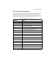
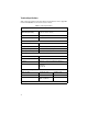
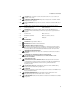
R.P.S. Input Connector Specifications
Table 5 lists the pin assignments for the R.P.S. Input connector on the back of
the switch. (Pin numbers 1 through 8 are the bottom row of pins on the
connector, with pin 1 in the bottom right corner. Pin numbers 9 through 16
are the top row, with pin 9 in the top right position on the connector.)
Table 5
RPS Input Port Pin Assignments
Pin Number Function
1 +12V dc
2 Remote Sense (RS) +5V dc
3 Remote Sense (RS) Ground
4 Remote Sense (RS) +3.3V dc
5 Redundant Power Supply (RPS) Present
6 Ground (+3.3V dc Return)
7 Ground (+5V dc Return)
8 +5V dc
9 Ground (+12V dc Return)
10 +3.3V dc
11 Ground (+3.3 dc Return)
12 +3.3V dc
13 Ground (+3.3V dc Return)
14 +3.3V dc
15 +5V dc
16 Ground (+5V dc Return)