AT-8800 SERIES SWITCH USER GUIDE Software Release 2.6.
AT-8800 Series Switch User Guide for Software Release 2.6.1 Document Number C613-02039-00 REV A. Copyright © 1999-2003 Allied Telesyn International, Corp. 960 Stewart Drive Suite B, Sunnyvale CA 94086, USA. All rights reserved. No part of this publication may be reproduced without prior written permission from Allied Telesyn. Allied Telesyn International, Corp. reserves the right to make changes in specifications and other information contained in this document without prior written notice.
Contents CHAPTER 1 Introduction Introducing the AT-8800 Series Switch .............................................................. 7 Why Read this User Guide? ............................................................................... 7 Where To Find More Information ...................................................................... 8 The AT-8800 Series Switch Documentation Set ........................................... 8 Online Technical Support ................................................
AT-8800 Series Switch User Guide The Diagnostics Menu .............................................................................. Changing the Password ............................................................................ Context Sensitive GUI Help ....................................................................... Saving Configuration Entered with the GUI .............................................. Combining GUI and CLI Configuration ....................................................
The Forwarding Process ............................................................................ 82 Layer 2 Filtering ........................................................................................ 83 The Egress Rules ....................................................................................... 85 Quality of Service ............................................................................................ 85 Spanning Tree Protocol (STP) ............................................
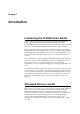
Chapter 1 Introduction Introducing the AT-8800 Series Switch Congratulations on purchasing an AT-8800 Series Intelligent Workgroup Switch. The AT-8800 Series Switch has been developed to meet the exceptionally high performance demands of low to mid-range applications and deliver low-latency high-bandwidth wirespeed Layer 2 and 3 switching. This guide introduces the AT-8800 Series Switch and will guide you through the most common uses and applications of your new switch.
AT-8800 Series Switch User Guide This user guide is organised into the following chapters: ■ Chapter 1, Introduction gives an overview of the switch features and of the documentation supplied with your switch. ■ Chapter 2, Getting Started with the Command Line Interface (CLI) describes how to gain access to the command lineinterface. ■ Chapter 3, Getting Started with the Graphical User Interface (GUI) describes how to access and use the graphical user interface, including troubleshooting the GUI.
Introduction 9 ■ AT-8800 Series Switch Documentation and Tools CD-ROM The AT-8800 Series Switch Documentation Set in Adobe Acrobat PDF format is bundled with every switch—the complete reference to installing, configuring and managing the switch, including detailed descriptions of all commands.
AT-8800 Series Switch User Guide Management Features The following features enhance management of the switch: ■ A sophisticated and configurable event logging facility for monitoring and alarm notification to single or multiple management centres. ■ Triggers for automatic and timed execution of commands in response to events. ■ Scripting for automated configuration and centralised management of configurations. ■ Dynamic Host Configuration Protocol (DHCP) for IP and IPv6.
Introduction 11 ■ Sophisticated packet filtering. ■ Bridging. ■ Van Jacobson’s header compression, STAC LZS and Predictor compression, and DES encryption. ■ Terminal serving using Telnet, with local host nicknames. ■ Access to network printers via LPD or TCP streams. ■ Resource Reservation Protocol (RSVP) for delivering quality of service to application data streams. ■ A fully featured, stateful inspection firewall. ■ IPsec-compliant IP security services.
AT-8800 Series Switch User Guide Most software features that require a special feature licence are bundled into one of the following special feature licence packs: ■ Full Layer 3 Feature Licence ■ Advanced Layer 3 Feature Licence ■ Security Pack Feature Licence For more information about purchasing special feature licences, contact your Allied Telesyn authorised distributor or reseller.
Chapter 2 Getting Started with the Command Line Interface (CLI) This Chapter This chapter describes how to access the switch’s CLI, and provides basic information about configuring the switch, including how to: ■ Physically connect a terminal or PC to the switch (see “Connecting a Terminal or PC” on page 14 and the Quick Install Guide). ■ Set the Terminal Communication parameters to match the router’s settings (see “Terminal Communication Parameters” on page 14).
AT-8800 Series Switch User Guide Connecting a Terminal or PC The first thing to do after physically installing the switch is to start a terminal or terminal emulation session to access the switch. Then you can use the command line interface (CLI) to configure the switch. If you wish to configure the switch using the Graphical User Interface, you must first access the CLI and assign an IP address to at least one interface.
Getting Started with the Command Line Interface (CLI) 15 If a modem is connected, configure the switch to make and/or accept calls via the modem. To set the CDCONTROL parameter to “CONNECT” and the FLOW parameter to “HARDWARE”, enter the command: SET ASYN CDCONTROL=CONNECT FLOW=HARDWARE If the terminal or modem is used with communications settings other than the default settings, then configure the asynchronous port to match the terminal or modem settings using the SET ASYN command.
AT-8800 Series Switch User Guide If IP addresses on your LAN are assigned dynamically by DHCP, you can set the switch to request an IP address from the DHCP server, using the commands: ADD IP INTERFACE=vlan1 IPADDRESS=DHCP ENABLE IP REMOTEASSIGN You do not need to set the MASK parameter because the subnet mask received from the DHCP server is used.
Getting Started with the Command Line Interface (CLI) 17 To add a static route, enter the command: ADD IP ROUTE=ipadd INTERFACE=interface NEXTHOP=ipadd [CIRCUIT=miox-circuit] [DLCI=dlci] [MASK=ipadd][METRIC=1..16] [METRIC1=1..16] [METRIC2=1..65535][POLICY=0..7] [PREFERENCE=0..
AT-8800 Series Switch User Guide ■ Do not use your birth date, street number or telephone number. ■ Do not write down your password anywhere. Make sure you remember the new password created as you cannot retrieve a lost password. Recovery of access to the switch is complex. Once you have logged into the manager account you are able to enter commands from this guide and from the AT-8800 Series Switch Software Reference.
Getting Started with the Command Line Interface (CLI) 19 Aliases The command line interface supports aliases. An alias is a short name for an often-used longer character sequence. When the user presses [Enter] to execute the command line, the command processor first checks the command line for aliases and substitutes the replacement text. The command line is then parsed and processed normally. Alias substitution is not recursive—the command line is scanned only once for aliases.
AT-8800 Series Switch User Guide Enabling Special Feature Licences You must enable the special feature licence you have purchased before you can use the licenced features. You will need the password provided by your authorised distributor or reseller. The advanced upgrade licence and password are different from the standard software release licence and password. The licence cannot be transferred from one switch to another.
Getting Started with the Graphical User Interface (GUI) 21 Chapter 3 Getting Started with the Graphical User Interface (GUI) This Chapter This chapter describes how to access the switch’s HTTP-based Graphical User Interface (GUI), and provides basic information about using the GUI, including: ■ What is the GUI? • ■ ■ Software Release 2.6.
AT-8800 Series Switch User Guide What is the GUI? The GUI (Graphical User Interface) is a web-based device management tool, designed to make it easier to configure and monitor the switch. The GUI provides an alternative to the CLI (Command Line Interface). Its purpose is to make complicated tasks simpler and regularly performed tasks quicker. The GUI relies on an HTTP server that runs on the switch, and a web browser on the host PC.
Getting Started with the Graphical User Interface (GUI) 23 To enable JavaScript in Netscape 6.2.x: 1. From the Edit menu, select Preference 2. Select the Advanced menu option. 3. Ensure that the “Enable JavaScript for Navigator” checkbox is checked. The minimum screen resolution on the PC is 800x600. HTTP Proxy Servers An HTTP proxy server provides a security barrier between a private network’s PCs and the Internet.
AT-8800 Series Switch User Guide Establishing a Connection to the Switch Before you start, consider how the switch fits into your network. If you are installing a new switch, consider whether you want to configure it before deploying it into the LAN, or want to configure it in situ. If you want to access a switch that has already been configured, consider the relative positions of the PC and the switch.
Getting Started with the Graphical User Interface (GUI) 25 Option 1: Configuring the Switch before Installation Use this procedure if: ■ You want to configure the switch before installing it in your LAN. ■ You will be installing the switch at a remote office or a customer site and want to configure it first. ■ You want a dedicated management PC permanently connected to the switch. 1.
AT-8800 Series Switch User Guide 9. At the login prompt, enter the user name and password The default username is manager: User Name: manager Password: friend The System Status page is displayed (Figure 6 on page 31). Select options from the sidebar menu to configure and manage the switch. Option 2: Installing the Switch into the LAN Use this procedure if: ■ You want to install the switch into the LAN before you configure it. 1.
Getting Started with the Graphical User Interface (GUI) 27 Figure 5: Configuring the switch from a PC in another subnet. gateway subnet subnet AT-8800 Series Switch You can browse to the switch through any VLAN, as long as you give that VLAN an IP address (see below). These instructions assume you will use vlan1. The switch ports all belong to vlan1 by default. 3. Access the switch’s command line interface Access the CLI from the PC, as described in “Connecting a Terminal or PC” on page 14. 4.
AT-8800 Series Switch User Guide 8. On the PC, bypass the HTTP proxy server, if necessary See “HTTP Proxy Servers” on page 23 for more information. 9. Point your web browser at the LAN interface’s IP address For normal access, point your web browser to http://ip-address For secure access, point your web browser to https://ip-address where ip-address is the interface’s IP address. 10.
Getting Started with the Graphical User Interface (GUI) 4. 29 Browse to the switch For normal access, point your web browser to http://ip-address where ip-address is the interface’s IP address. To access the switch securely if SSL (Secure Sockets Layer) has been configured on the interface, point your web browser to https://ip-address For more information about secure access, see “Secure Access” on page 29. 5.
AT-8800 Series Switch User Guide 2. Login as a Security Officer To login as the user with Security Officer privilege called “CIPHER”, use the command: LOGIN CIPHER And then enter the password for “CIPHER”, “sbr4y3”. 3. Enable system security To enable system security, use the command: ENABLE SYSTEM SECURITY 4. Create an RSA key pair for this switch. To create an RSA key pair, use the command: CREATE ENCO KEY=0 TYPE=RSA LENGTH=1024 5. Set the switch’s distinguished name.
Getting Started with the Graphical User Interface (GUI) 31 10. Configure an IP interface to run SSL over To configure an IP interface that SSL will be run over, first enable IP using the command: ENABLE IP To make VLAN1 the IP interface, and 172.30.1.105 the interface’s IP address, use the command: ADD IP INTERFACE=vlan1 IP=172.30.1.105 To add an IP route on this interface with a next hop of 172.30.1.254, use the command: ADD IP ROUTE=0.0.0.0 INTERFACE=vlan1 NEXT=172.30.1.
AT-8800 Series Switch User Guide Using the GUI: Navigation and Features The GUI consists of a large number of pages, which you navigate between using the menu on the left of the browser window. This section describes how to use the GUI, and gives an overview of its functionality.
Getting Started with the Graphical User Interface (GUI) 33 To modify an existing item, select it by clicking on the option button at the beginning of its entry in the selection table. Then click the Modify button. This opens the popup “modify” page, which lets you expand or change the configuration (for example, change the Hello interval for a PIM interface; see Figure 9 on page 34).
AT-8800 Series Switch User Guide Figure 9: An example of a popup “modify” page Non-editable field Editable Fields GUI pages allow you to enter values or select options through a range of field types. These include: • text fields, to enter character strings or numbers, especially for fields where there are few limits on the entries (such as names). See the online help for valid characters and field length • select lists, to select one option from a small number of possibilities.
Getting Started with the Graphical User Interface (GUI) 35 Apply Button An Apply button applies the configuration settings on the page or the section of the page. The new settings will take effect immediately, but are not automatically saved. To save the settings after clicking Apply, click the Save button above the menu. Cancel Button A Cancel button closes a popup page without making any changes to the configuration.
AT-8800 Series Switch User Guide The Diagnostics Menu The GUI’s diagnostics pages enable you to troubleshoot network problems and observe traffic flow, including: • displaying the number of good and bad packets received and transmitted over each switch port • displaying the number and type of PPP packets received and transmitted • displaying the number and type of packets received and transmitted by IP, and discarded by the IP gateway • displaying the number and type of ICMP and UDP packets rece
Getting Started with the Graphical User Interface (GUI) 37 Saving Configuration Entered with the GUI Save button Configuration changes applied using the GUI can be saved to a configuration script by clicking the Save button at the top of the sidebar menu. A pop-up Save window gives you the option of saving to the current configuration file, another existing file, or a new file. You can also choose to use this configuration at bootup.
AT-8800 Series Switch User Guide Upgrading the GUI You can download the latest GUI resource file from the support site at http://www.alliedtelesyn.co.nz. Before you start, ensure that the switch is running the most recent release and patch files. The GUI is not part of the firmware release file, but the most recent resource file will generally only be compatible with the most recent software release.
Getting Started with the Graphical User Interface (GUI) 39 When the switch has loaded the file into its RAM, it displays the message “File transfer successfully completed”. It then writes the file to FLASH memory, which takes approximately 30 seconds after the message. Once the file has been copied to FLASH, you can enter commands that refer to it. 3.
AT-8800 Series Switch User Guide Deleting Temporary Files Browsers store local copies of web pages as temporary files. If you upgrade to a new GUI resource file, or if you encounter problems in browsing to the GUI, you may need to delete these files (clear the cache). To clear the cache in Internet Explorer: 1. From the Tools menu, select Internet Options. 2. On the General tab, click the Delete Files button. 3. The Delete Files dialog box opens. Click the OK button.
Getting Started with the Graphical User Interface (GUI) 41 Problem The GUI is behaving inconsistently, or you cannot access some pages. Solution ■ Delete your browser’s temporary files (see “Deleting Temporary Files” on page 40) and try again. ■ Check that you are trying to access the GUI from a supported operating system and browser combination. See “Browser and PC Setup” on page 22 for more information. ■ Check that JavaScript is enabled.
AT-8800 Series Switch User Guide IP Addresses and DHCP Problem The switch is enabled as a DHCP server, but cannot assign an IP address to a host. Solution ■ Reboot the host machine. ■ Check the host’s TCP/IP settings, to make sure that the host is set to obtain its IP address dynamically: In Windows 95/98, click Settings > Control Panel > Network. Select TCP/ IP and click Properties. Click Obtain an IP address automatically.
Getting Started with the Graphical User Interface (GUI) 43 Loading Software Problem You have attempted to load a new release file onto the switch, but the load has failed and you cannot access the switch through the GUI. Solution 1. Access the switch’s CLI (see “Connecting a Terminal or PC” on page 14). If the switch has been switched off or has rebooted since you attempted to load the release file, it will boot up with the default installation. This contains the commands you require to load a file.
Chapter 4 Operating the switch This Chapter This chapter introduces basic operations on the switch, including: ■ “User Accounts and Privileges” on page 45 ■ “Normal Mode and Security Mode” on page 47 ■ “Remote Management” on page 49 ■ “Storing Files in FLASH Memory” on page 49 ■ “Using Scripts” on page 50 ■ “Loading and Uploading Files” on page 52 ■ “Upgrading Switch Software” on page 56 ■ “Using the Built-in Editor” on page 60 ■ “SNMP and MIBs” on page 60 User Accounts and Privileges Th
AT-8800 Series Switch User Guide In normal mode, a user with manager privilege can create and delete accounts for users with any of these privilege levels. Users and passwords are managed by the User Authentication Facility. Users and passwords are authenticated using an internal database called the User Authentication Database, or by interrogation of external RADIUS (Remote Authentication Dial In User Service) or TACACS (Terminal Access Controller Access System) servers.
Operating the switch 47 See the Operations chapter in the AT-8800 Series Switch Software Reference for: ■ More information about managing and using accounts with user, manager and security officer privileges ■ A full list of commands that require security officer privilege when the switch is in secure mode ■ Information about enabling a remote security officer. Normal Mode and Security Mode The switch operates in one of two modes, either normal mode or security mode.
AT-8800 Series Switch User Guide When the switch is in security mode, a user with security officer privilege is the only person who can execute commands which affect switch security. Table 5 on page 48 lists commands that only a security officer can execute when the switch is in security mode. A complete list of commands limited by security mode are listed in the Operation chapter in the AT-8800 Series Switch Software Reference.
Operating the switch 49 Table 5: Commands requiring SECURITY OFFICER privilege when the switch is operating in security mode (Continued). Command Specific Parameters SHOW FILE SHOW PPP CONFIG UPLOAD Remote Management You can manage remote switches as easily as you manage the local switch a terminal is connected to. From a terminal connected to any port (with either USER or MANAGER privilege), enter the command: TELNET ipadd to Telnet to the remote switch, specifying the remote router’s IP address.
AT-8800 Series Switch User Guide extensions of 3 characters. For example, the file extralongfilenam.cfg may be saved as extral~1.cfg in the FLASH File System. Therefore, files can be accessed via two file names, either of which can be used for file management. A translation table, named longname.lfn, converts file names between DOS 16.3 format and DOS 8.3 format. To reconcile file names the switch consults the translation table which is synchronised with file contents in memory.
Operating the switch 51 In addition to the boot configuration script that the switch automatically runs when it restarts, you can run a configuration script manually at any time, by entering the command: ACTIVATE SCRIPT=filename You can also set a trigger to automatically execute a configuration script when a specified event occurs. For more information about how to create and run scripts, see the Scripting chapter in the AT-8800 Series Switch Software Reference.
AT-8800 Series Switch User Guide Loading and Uploading Files When you want to upgrade your switch to a new software patch or release, or use a new configuration file, load files onto the switch using the router’s LOADER module. You can also use the LOADER module to upload files, such as configuration files or log files, from the switch onto a host on the network. File Naming Conventions The file subsystem provides a flat file system—directories are not supported.
Operating the switch 53 Table 6: File extensions and file types (Continued). Extension File type/function SPA Spam Mail Source files, listing email addresses, identified as spam mail sources, to be blocked by the firewall SMTP proxy, if it is active. SPL VPN client. TXT Generic text file. VPF Future VPN client. LFN Extension used for the long file name translation table You may see files on your switch with file name extensions not listed in Table 6 on page 52.
AT-8800 Series Switch User Guide Setting LOADER Defaults You are likely to repeat the process of downloading files onto the switch using a similar method each time. You can set defaults for some or all of the LOADER parameters. You can then use or override some or all of these defaults for each particular load.
Operating the switch 55 Uploading Files From the Switch The LOADER can upload files from the switch to a network host, using TFTP or ZMODEM. Upload files using one of the commands: UPLOAD [METHOD=TFTP] [FILE=filename] [SERVER={hostname|ipadd}] UPLOAD [METHOD=ZMODEM] [FILE=filename] [ASYN=port] The UPLOAD command uses defaults set with the SET LOADER command, for parameters not specified with the upload command.
AT-8800 Series Switch User Guide Upgrading Switch Software When you first start the switch, it automatically loads the software release from FLASH memory into RAM, where the CPU uses it to run all the router’s software features. The switch may also load a patch file to improve the main release. The software release and any patch files are current when the switch is produced at the factory.
Operating the switch 57 when the switch boots correctly, to then set up the preferred install with the new release or patch. To change the install information in the switch, enter the command: SET INSTALL={TEMPORARY|PREFERRED|DEFAULT} [RELEASE={release-name|EPROM}] [PATCH=patch-name] For security reasons the SET INSTALL command is only accepted if the user has SECURITY OFFICER privilege.
AT-8800 Series Switch User Guide on page 52). To load the release file using your LOADER default settings, enter the command: LOAD FILE=86s-262.rez Wait for the release to load. This can take several minutes, even if you are loading the file over a high speed link. To see the progress of the load, enter the command: SHOW LOAD To check that the files are successfully loaded, enter the command: SHOW FILE 3. Enter licence information for the release.
Operating the switch 59 Example: Upgrade to a new patch file Use this procedure to upgrade the software release currently running on the switch with a new patch. This example assumes that the current release, Software Release 2.6.1, is set as the preferred release. To upgrade to a new patch file: 1. Load the new patch file onto the switch. Load the new file onto your switch. See “Loading and Uploading Files” on page 52. LOAD FILE=86261-01.paz Check that the file is successfully loaded. SHOW FILE 2.
AT-8800 Series Switch User Guide Using the Built-in Editor The AT-8800 Series Switch has a built-in full-screen text editor for editing script files stored on the switch file subsystem. Using the text editor you can run script files manually, or set script files to run automatically at switch restart, or on trigger events. Figure 11 on page 60 shows a example screen shot of the text editor.
Operating the switch 61 SNMP communities are the main configuration item in the router’s SNMP agent, and are defined in terms of a list of IP addresses which define the SNMP application entities (trap hosts and management stations) in the community. To create an SNMP community, enter the command: CREATE SNMP COMMUNITY=name [ACCESS={READ|WRITE}] [TRAPHOST=ipadd] [MANAGER=ipadd] [OPEN={ON|OFF|YES|NO|TRUE|FALSE}] The community name is a security feature and you should keep it secure.
AT-8800 Series Switch User Guide See other chapters in the AT-8800 Series Switch Software Reference for more information on how to: ■ Use the logging facility to monitor network activity and to select and display the results (see the Logging Facility chapter). ■ Use SNMP to manage the switch remotely (see the Simple Network Management Protocol (SNMP) chapter and Appendix C: SNMP MIBs). ■ Use the command line to create, delete and modify configuration scripts (see the Scripting chapter).
Chapter 5 Layer 2 Switching This section describes the Layer 2 switching features on the AT-8800 Series Switch, and how to configure them. Switch Ports Each Ethernet switch port is uniquely identified by a port number. The switch supports a number of features at the physical level that allow it to be connected in a variety of physical networks. This physical layer (layer 1) versatility includes: ■ Enabling and disabling of Ethernet ports.
AT-8800 Series Switch User Guide To enable or disable a switch port, use the commands: ENABLE SWITCH PORT={port-list|ALL} DISABLE SWITCH PORT={port-list|ALL} Resetting Ethernet ports at the hardware level discards all frames queued for reception or transmission on the port, and restarts autonegotiation of port speed and duplex mode.
Layer 2 Switching 65 Table 7: Parameters in the output of the SHOW SWITCH PORT command Parameter Meaning Configured speed/duplex The port speed and duplex mode configured for this port. One of “Autonegotiate” or a combination of a speed (one of “10 Mbps”, “100 Mbps” or “1000 Mbps”) and a duplex mode (one of “half duplex” or “full duplex”). Actual speed/duplex The port speed and duplex mode that this port is actually running at.
AT-8800 Series Switch User Guide Autonegotiation of Port Speed and Duplex Mode Each of the switch ports can operate at either 10 Mbps or 100 Mbps, in either full duplex or half duplex mode. In full duplex mode a port can transmit and receive data simultaneously, while in half duplex mode the port can either transmit or receive, but not at the same time. This versatility makes it possible to connect devices with different speeds and duplex modes to different ports on the switch.
Layer 2 Switching 67 Table 8: Port speed and duplex settings for Ethernet Ports . AT-8824 AT-8848 Speed 10/100 10MHALF Yes 10MFULL Yes 100MHALF Yes 100MFULL Yes 1000MHALF No 1000MFULL No 10MHAUTO Yes 10MFAUTO Yes 100MHAUTO Yes 100MFAUTO Yes 1000MHAUTO No 1000MFAUTO No AUTONEGOTIATE Yes The SHOW SWITCH PORT command displays the port speed and duplex mode settings.
AT-8800 Series Switch User Guide which the whole trunk group belongs, unless it is first removed from the trunk group. The members of a trunk group can be specified when it is created, and ports can be added to or removed from a trunk group using the commands: ADD SWITCH TRUNK=trunk PORT=port-list DELETE SWITCH TRUNK=trunk PORT={port-list|ALL} Ports which are members of a trunk group must operate in full duplex mode.
Layer 2 Switching 69 Packet Storm Protection The packet storm protection feature allows the user to set limits on the reception rate of broadcast, multicast and destination lookup failure packets. The software allows separate limits to be set for each port, beyond which each of the different packet types are discarded. The software also allows separate limits to be set for each of the packet types. Which of these options can be implemented depends on the model of switch hardware.
AT-8800 Series Switch User Guide the BCLIMIT parameter description for important information about packet rate limiting. The default value for this parameter is NONE. If packet storm protection limits are set on the switch, the PORT parameter must specify complete processing blocks. The ability of the switch to limit packet reception rates for different classes of packets is dependent on the particular switch hardware.
Layer 2 Switching 71 To send packets that match particular criteria to the mirror port, first create a classifier or classifiers using the command: CREATE CLASSIFIER Then create a hardware filter with the ACTION parameter set to SENDMIRROR, using the command: ADD SWITCH HWFILTER CLASSIFIER=classifier-list ACTION=SENDMIRROR By default mirroring is disabled, no mirror port is set, and no source ports are set to be mirrored.
AT-8800 Series Switch User Guide Table 9: Example output from the SHOW SWITCH PORT INTRUSION command.
Layer 2 Switching 73 Devices that are members of the same VLAN only exchange data with each other through the switch’s switching capabilities. To exchange data between devices in separate VLANs, the switch’s routing capabilities are used. The switch passes VLAN status information, indicating whether a VLAN is up or down, to the Internet Protocol (IP) module. IP uses this information to determine route availability. The switch has a maximum of 255 VLANs, ranging from a VLAN identifier (VID) of 1 to 4094.
AT-8800 Series Switch User Guide Figure 13: Format of user priority and VLAN data in an Ethernet frame. Destination Address 64 bits 48 bits TPID 16 bits Source Type/ Address Length Frame Data 48 bits 16 bits User Priority CFI 3 bits 1 bit Preamble 368-12000 CRC 32 bits VID 12 bits 0x81-00 SWITCH6 Table 11: Reserved VID values . VID value (hexadecimal) Meaning and use of reserved VID values 0 The null VLAN ID.
Layer 2 Switching 75 Every frame admitted by the switch has a VID associated with it. If a frame arrives on a tagged port, the associated VID is determined from the VLAN tag the frame had when it arrived. If a frame arrives on an untagged port, it is associated with the VID of the VLAN for which the incoming port is untagged. When the switch forwards a frame over a tagged port, it adds a VLAN tag to the frame.
AT-8800 Series Switch User Guide Figure 14: VLANs with tagged ports. Training VLAN VID=3 Port 3 Port 22 Port 26 Switch A Port 21 Switch B Port 25 Port 1 Port 4 Port 2 Port 23 Admin VLAN VID=2 Marketing VLAN VID=4 411 VLAN-aware server SWITCH3 Table 12: VLAN membership of example of a network using tagged ports.
Layer 2 Switching 77 If the network includes VLANs that do not need to share network resources or span several switches, VLAN membership can usefully be based on untagged ports. Otherwise, VLAN membership should be determined by tagging (see “VLAN Tagging” on page 73). Figure 15 on page 77 shows two port-based VLANs with untagged ports belonging to them. Ports 1-3 belong to the marketing VLAN, and ports 14-16 belong to the training VLAN.
AT-8800 Series Switch User Guide To add tagged ports to a VLAN, use the command: ADD VLAN={vlan-name|1..4094} PORT={port-list|ALL} FRAME=TAGGED A port can be tagged for any number of VLANs. To add untagged ports to a VLAN, use the command: ADD VLAN={vlan-name|1..4094} PORT={port-list|ALL} [FRAME=UNTAGGED] A port can be untagged for zero or one VLAN. A port can only be added to the default VLAN as an untagged port if it is not untagged for another VLAN.
Layer 2 Switching 79 Summary of VLAN tagging rules When designing a VLAN and adding ports to VLANs, the following rules apply. 1. Each port, except for the mirror port, must belong to at least one static VLAN. By default, a port is an untagged member of the default VLAN. 2. A port can be untagged for zero or one VLAN. A port that is untagged for a VLAN transmits frames destined for that VLAN without a VLAN tag in the Ethernet frame. 3. A port can be tagged for zero or more VLANs.
AT-8800 Series Switch User Guide Generic VLAN Registration Protocol (GVRP) The GARP application GVRP allows switches in a network to dynamically share VLAN membership information, to reduce the need for statically configuring all VLAN membership changes on all switches in a network. See the Generic Attribute Registration Protocol (GARP) chapter in the Rapier Switch Software Reference. Layer 2 Switching Process The Layer 2 switching process comprises related but separate processes.
Layer 2 Switching 81 The default settings for the Ingress Rules are to Admit All Frames, and for Ingress Filtering to be OFF. This means that if no VLAN configuration has been done, all incoming frames pass on to the Learning Process, regardless of whether or not they are VLAN tagged. The parameters for each port’s Ingress Rules can be configured using the command: SET SWITCH PORT={port-list|ALL} [ACCEPTABLE={VLAN|ALL}] [INFILTERING={ON|OFF}] [other-parameters...
AT-8800 Series Switch User Guide If the frame’s source address is not already in the Forwarding Database for the VLAN, the address is added and an ageing timer for that entry is started. If the frame’s source address is already in the Forwarding Database, the ageing timer for that entry is restarted.
Layer 2 Switching 83 the switch floods the frame on all ports in the VLAN except the port on which the frame was received. If the destination address is found, the switch discards the frame if the port is not in the STP ‘Forwarding’ state, if the destination address is on the same port as the source address, or if there is a static filter entry for the destination address set to DISCARD (“Layer 2 Filtering” on page 83). Otherwise, the frame is forwarded on the indicated port.
AT-8800 Series Switch User Guide Figure 16: Example output from the SHOW SWITCH FILTER command.
Layer 2 Switching 85 The Egress Rules Once the Forwarding Process has determined which ports and transmission queues to forward a frame from, the Egress Rules for each port determine whether or not the outgoing frame is VLAN-tagged with its numerical VLAN Identifier (VID). (See “Virtual Local Area Networks (VLANs)” on page 72). When a port is added to a VLAN, it is configured to transmit either untagged or VLAN tagged packets, using the command: ADD VLAN={vlanname|1..
AT-8800 Series Switch User Guide To display the mapping of user priority to QOS egress queues, use the command: SHOW SWITCH QOS Figure 17: Example output from the SHOW SWITCH QOS command Priority Level QOS egress queue ------------------------------------0 ................... 1 1 ................... 0 2 ................... 0 3 ................... 1 4 ................... 2 5 ................... 2 6 ................... 3 7 ...................
Layer 2 Switching 87 A spanning tree running in standard mode can take up to one minute to rebuild after a topology or configuration change. The Rapid Spanning Tree algorithm provides for a more rapid recovery of connectivity following the failure of a bridge, bridge port, or a LAN. For information about RSTP see the Rapid Mode Spanning Tree Types section, Switch chapter in the Rapier Switch Software Reference.
AT-8800 Series Switch User Guide To specify whether the STP will operate in STANDARD mode or RAPID mode, use the command: SET STP={stp-name|ALL} [MODE={STANDARD|RAPID}] [other parameters] The default is STANDARD. If the mode is changed while the algorithm is running then the STP is re-initialised.
Layer 2 Switching 89 by the Root Bridge. The FORWARDDELAY, MAXAGE and HELLOTIME parameters are interrelated. See the note and formulae below. The default value for FORWARDDELAY is 15 seconds. The HELLOTIME parameter sets the time, in seconds, between the transmission of switch spanning tree configuration information when the switch is the Root Bridge of the spanning tree or is trying to become the Root Bridge. The default value is 2 seconds.
AT-8800 Series Switch User Guide Figure 18: Example output from the SHOW STP command. STP Information -----------------------------------------------------------Name .................. grey Mode .................. Rapid RSTP Type ............. Normal VLAN members .......... vlan4 (4) Status ................ ON Number of Ports ....... 2 Number Enabled ...... 2 Number Disabled ..... 0 Bridge Identifier ..... 32768 : 00-00-cd-05-19-28 Bridge Priority ....... 32768 Root Bridge ...........
Layer 2 Switching 91 Table 18: Parameters in the output of the SHOW STP command . Software Release 2.6.1 C613-02039-00 REV A Parameter Meaning STP Name The name of the Spanning Tree Protocol entity. Mode Whether STP is running in standard, or rapid mode. RSTP Type Whether RSTP is operating normally, or as STP compatible. In STP compatible mode, the rapid transitions to forwarding do not occur. VLAN members A list of the VLANs that are members of the STP. VLAN Identifiers are shown in brackets.
AT-8800 Series Switch User Guide Table 18: Parameters in the output of the SHOW STP command (Continued). Parameter Meaning Switch Max Age The value of the Max Age parameter when this switch is the Root or is attempting to become the Root. This parameter is set by the MAXAGE parameter in the SET STP command. Switch Hello Time The value of the Hello Time parameter when this switch is the Root or is attempting to become the Root.
Layer 2 Switching 93 so that a port operating at 10Mbps has a default pathcost of 100, a port operating at 100 Mbps has a default pathcost of 10, and a port operating at 1 Gbps has a default pathcost of 1. Setting the pathcost to a larger value on a particular port is likely to reduce the traffic over the LAN connected to it. This may be appropriate if the LAN has lower bandwidth, or if there are reasons for limiting the traffic across it.
AT-8800 Series Switch User Guide Figure 19: Example output from the SHOW STP PORT command. STP Port Information -----------------------------------------------------------STP ..................... grey STP Status ............ ON Port .................. 3 RSTP Port Role ...... Disabled State ............... Discarding Point To Point ...... No (Auto) Port Priority ....... 128 Port Identifier ..... 8003 Pathcost ............ 200000 Designated Root ..... 32768 : 00-00-cd-05-19-28 Designated Cost .....
Layer 2 Switching 95 Table 19: Parameters displayed in the output of the SHOW STP PORT command . Parameter Meaning STP The name of the STP that the port is a member of. STP Status Whether this STP is enabled or disabled; one of ON or OFF. Port The number of the port. RSTP Port Role The role of the port; one of Disabled, Alternate, Backup, Designated, or Root. (Rapid Mode only).
AT-8800 Series Switch User Guide Figure 20: Example output from the SHOW STP COUNTER command STP Counters -----------------------------------------------------------STP Name: default Receive: Transmit: Total STP Packets 0 Total STP Packets 1677 Configuration BPDU 0 Configuration BPDU 0 TCN BPDU 0 TCN BPDU 0 RST BPDU 0 RSTP BPDU 1677 Invalid BPDU 0 Discarded: Port Disabled 0 Invalid Protocol 0 Invalid Type 0 Invalid Message Age 0 Config BPDU length 0 TCN BPDU length 0 RST BPDU length 0 -----------------
Layer 2 Switching 97 Table 20: Parameters in the output of the SHOW STP COUNTER command Parameter Meaning Config BPDU length The number of Configuration BPDUs that had an incorrect length. TCN BPDU length The number of Topology Change Notification BPDUs that had an incorrect length. RST BPDU length The number of Rapid Spanning Tree BPDUs that had an incorrect length (RAPID mode only).
AT-8800 Series Switch User Guide out all ports. IGMP snooping is independent of the IGMP and Layer 3 configuration, so an IP interface does not have to be attached to the VLAN, and IGMP does not have to be enabled or configured. IGMP snooping is enabled by default. To disable it, use the command: DISABLE IGMPSNOOPING Disabling IGMP snooping may be useful if filters are used extensively, because IGMP snooping uses a Layer 3 filter. When IGMP snooping is disabled, this filter becomes available.
Layer 2 Switching 99 Figure 21: Example output from the SHOW IP IGMP command. IGMP Protocol ---------------------------------------------------------------------------------Status ........................... Enabled Default Query Interval ........... 125 secs Default Timeout Interval ......... 270 secs Last Member Query Interval ....... Last Member Query Count .......... Robustness Variable .............. Query Response Interval .......... 10 (1/10secs) 2 2 100 (1/10secs) Interface Name ..........
AT-8800 Series Switch User Guide Triggers The Trigger Facility can be used to automatically run specified command scripts when particular triggers are activated. When a trigger is activated by an event, global parameters and parameters specific to the event are passed to the script that is run. For a full description of the Trigger Facility, see the Trigger Facility chapter in the Rapier Switch Software Reference.
Chapter 6 Layer 3 The AT-8800 Series Switch routes IP and IP multicasting traffic at wire speed between VLANs, and supports a number of other Layer 3 protocols. Once a VLAN has been created (see “Virtual Local Area Networks (VLANs)” on page 72), the VLAN name can be used wherever a logical interface is required in commands for configuring routing protocols. VLAN names are of the form: VLAN-vlanname or VLANn where vlanname is the manager-assigned name of the VLAN, and n is the VLAN identifier (VID).
AT-8800 Series Switch User Guide Internet Protocol (IP) The switch performs IP routing at wire speed between VLANs that have been configured as IP interfaces. For example, to add the admin VLAN as an IP interface, giving it an IP address of 192.168.163.39 in the subnet 192.168.163.0, first enable IP using the command: ENABLE IP Then use either of the following commands: ADD IP INTERFACE=vlan-admin IPADDRESS=192.168.163.39 MASK=255.255.255.0 ADD IP INTERFACE=vlan11 IPADDRESS=192.168.163.39 MASK=255.
Layer 3 103 Routing Information Protocol (RIP) Routing protocols such as RIPv1 and RIPv2 can be enabled on a VLAN. For example, to enable RIPv2 on the admin VLAN, use the command: ADD IP RIP INTERFACE=vlan11 SEND=RIP2 RECEIVE=BOTH To display information about RIP (Figure 23 on page 103), use the command: SHOW IP RIP Figure 23: Example output from the SHOW IP RIP command.
AT-8800 Series Switch User Guide Figure 24: Example output from the SHOW IPX CIRCUIT command. IPX CIRCUIT information Name ......................... Status ....................... Interface .................... Network number ............... Station number ............... Link state ................... Cost in Novell ticks ......... Type20 packets allowed ....... On demand .................... Circuit 1 enabled vlan11 (802.
Layer 3 105 Figure 25: Example output from the SHOW APPLE PORT command. Appletalk Port Details -----------------------------------Port Number .............. 1 Interface ................ vlan11 ifIndex .................. 1 Node ID .................. 217 Network Number ........... 22 Network Range Start ...... 22 Network Range End ........ 22 State .................... ACTIVE Seed ..................... NO Seed Network Start ....... 0 Seed Network End ......... 0 Hint ..................... YES Hint Node ID .
Chapter 7 Maintenance and Troubleshooting This Chapter If you are familiar with networking and switch operations, you may be able to diagnose and solve some problems yourself. This chapter gives tips on how to: ■ start your switch (see “How the Switch Starts Up” on page 108). ■ avoid problems (see “How to Avoid Problems” on page 109). ■ reconfigure your switch if you accidentally clear the FLASH memory (see “What to Do if You Clear FLASH Memory Completely” on page 111).
AT-8800 Series Switch User Guide How the Switch Starts Up The sequence of operations that the switch performs when it boots are: 1. Perform startup self tests. 2. Perform the install override option. 3. Load the FLASH boot release as the INSTALL boot. 4. Inspect and check INSTALL information. 5. Load the required release as the main boot. 6. Start the switch. 7. Execute the boot script, if one has been configured.
Maintenance and Troubleshooting 109 Table 22: Switch startup sequence keystrokes. Pressing key... Forces the switch to... Y Load the FLASH boot release, with no patch, and skip straight to step 6. S Start with the default configuration. Any boot script or NVS configuration is ignored. N Configure from NVS, ignoring any boot script. [Ctrl/D] Enter diagnostics mode. When you start the switch the FLASH boot release is always loaded first.
AT-8800 Series Switch User Guide Backup switch If your network has many switches, you may wish to keep a backup switch ready to replace any switch that malfunctions. When you upgrade the software release or patch on the other switches in the network, upgrade the backup too. Store on it one current config script for each switch in your network, so that when it is needed, you need only set the configuration file with which it boots to match the switch it replaces.
Maintenance and Troubleshooting 111 What to Do if You Clear FLASH Memory Completely DO NOT clear the FLASH memory completely. The software release files are stored in FLASH, and clearing it would leave no software to run the switch. If you accidentally do this, you will need to: 1. Boot with default configuration. Reboot the switch from a terminal connected the asynchronous terminal port (not Telnet). Use the install override to run the default configuration (see “How the Switch Starts Up” on page 108).
AT-8800 Series Switch User Guide What to Do if the PPP Link Disconnects Regularly If the device at the other end of the PPP link is not an ATR router or switch but is supplied by another vendor turn LQR (Link Quality Reporting) off on PPP links (LQR=OFF) and instead use LCP Echo Request and Echo Reply messages to determine link quality (ECHO=ON).
Maintenance and Troubleshooting ■ 113 To get debugging output, enter the command: SHOW DEBUG ■ Depending on the problem, the support personnel may also ask you for the output from the following commands (see the Monitoring and Fault Diagnosis section in the Operations chapter, AT-8800 Series Switch Software Reference): SHOW EXCEPTION SHOW STARTUP SHOW LOG SHOW CPU SHOW BUFFER Resetting Switch Defaults To restart the switch at any time with no configuration, enter the command: RESTART SWITCH CONFIG=NON
AT-8800 Series Switch User Guide To set PING defaults, enter the command: SET PING [{[IPADDRESS=]ipadd|[IPXADDRESS=]network:station| [APPLEADDRESS=]network.node}] [LENGTH=number] [NUMBER={number|CONTINUOUS}] [PATTERN=hexnum] [{SIPADDRESS=ipadd|SIPXADDRESS=network:station|SAPPLEADDR ESS=network.
Maintenance and Troubleshooting 115 The “IP Packet Forwarding” field in the output should be set to “Enabled”. Refer to the documentation for the host TCP/IP software for more information about configuring a gateway. The host’s TCP/IP software should be configured to use the Head Office switch as its gateway. Refer to the documentation for the host TCP/IP software for more information about configuring a gateway. 3.
AT-8800 Series Switch User Guide Troubleshooting IPX Configurations No Routes are Visible to the Remote Router 1. Check the PPP link To check that the PPP link is active, enter the command: SHOW PPP The display should look like that shown in Figure 28 on page 116. The state of the IPX control protocol (IPXCP) should be “OPENED”. If not, then the fault lies with the connection between the two switches, or the PPP configuration at either end of the link.
Maintenance and Troubleshooting 3. 117 Check for file server on Remote Office switch Does the file server appear in the IPX service table of the Remote Office switch? If the server does not appear in the table, its presence is not advertised to the local LAN. To check this, enter the command: SHOW IPX SERVICE This should produce a display like that shown in Figure 29 on page 117.
AT-8800 Series Switch User Guide Any parameters not specified use the defaults configured with a previous invocation of the command: SET TRACE [[IPADDRESS=]ipadd] [MAXTTL=number] [MINTTL=number] [NUMBER=number] [PORT=port-number] [SCREENOUTPUT={YES|NO}] [SOURCE=ipadd] [TIMEOUT=number] [TOS=number] As each response packet is received a message is displayed on the terminal device from which the command was entered and the details are recorded.