AT-2911GP Network Adapters Gigabit Fiber Ethernet PoE+ Adapters AT-2911GP/SXLC AT-2911GP/SXSC AT-2911GP/LXLC AT-2911GP/LXSC Installation and User’s Guide 613-001872 Rev.
Copyright © 2013 Allied Telesis, Inc. All rights reserved. No part of this publication may be reproduced without prior written permission from Allied Telesis, Inc. Microsoft and Internet Explorer are registered trademarks of Microsoft Corporation. Netscape Navigator is a registered trademark of Netscape Communications Corporation. All other product names, company names, logos or other designations mentioned herein are trademarks or registered trademarks of their respective owners. Allied Telesis, Inc.
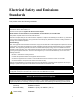
Electrical Safety and Emissions Standards This product meets the following standards: . U.S. Federal Communications Commission Declaration of Conformity Manufacturer Name: Allied Telesis, Inc. Declares that the product: Gigabit Fiber Ethernet PoE+ Adapter Model Numbers: AT-2911GP/SXLC, AT-2911GP/SXSC, AT-2911GP/LXLC, AT-2911GP/LXSC This product complies with FCC Part 15B, Class B Limits: This device complies with part 15 of the FCC Rules.
Translated Safety Statements Important: The indicates that a translation of the safety statement is available in a PDF document titled “Translated Safety Statements” posted on the Allied Telesis website at: www.alliedtelesis.com/support/.
Contents Preface ..................................................................................................................................................................................9 Safety Symbols Used in this Document................................................................................................................................10 Contacting Allied Telesis .........................................................................................................................
AT-2911GP Gigabit Fiber Ethernet PoE+ Adapters Installation and User’s Guide Performing the Silent Installation ..........................................................................................................................................60 Installing the Driver Silently ...........................................................................................................................................60 Viewing Supported DPInst Options .....................................................
Contents VMQ VLAN Filtering ...........................................................................................................................................................127 Wake Up Capabilities .........................................................................................................................................................128 Wake on Magic Packet ..............................................................................................................................
AT-2911GP Gigabit Fiber Ethernet PoE+ Adapters Installation and User’s Guide 8
Preface This manual is the installation and user’s guide for the AT-2911GP Gigabit Fiber Ethernet PoE+ Adapter cards.
AT-2911GP Gigabit Fiber Ethernet PoE+ Adapters Installation and User’s Guide Safety Symbols Used in this Document This document uses the following conventions: Note Notes provide additional information. Caution Cautions inform you that performing or omitting a specific action may result in equipment damage or loss of data. Warning Warnings inform you that performing or omitting a specific action may result in bodily injury.
Preface Contacting Allied Telesis If you need assistance with this product, you may contact Allied Telesis technical support by going to the Support & Services section of the Allied Telesis web site at www.alliedtelesis.com/support.
AT-2911GP Gigabit Fiber Ethernet PoE+ Adapters Installation and User’s Guide 12
Chapter 1 Introduction This chapter provides an introduction to the Allied Telesis AT-2911GP Gigabit Fiber Ethernet PoE+ Adapter cards.
AT-2911GP Gigabit Fiber Ethernet PoE+ Adapters Installation and User’s Guide Description The AT-2911GP adapter is a Gigabit Ethernet PCI Express (PCIe) card developed based on Broadcom’s BCM5718 Ethernet controller. The adapter card is equipped with one 1000SX or 1000LX fiber optic port and one 10/100/1000T Power over Ethernet Plus (PoE+) copper port capable of providing electrical power to Class 4 devices. The AT-2911GP adapter card can be used as a dual port adapter or a bridge that connects two ports.
Chapter 1: Introduction Dual Port Adapter The AT-2911GP adapter is a dual port adapter to connect a PC to two separate networks. You can assign an IP address to each port. After you physically install the AT-2911GP adapter on your Windows operating system, you must install driver software. To install driver software, see Chapter 3, “Installing the Driver Software” on page 35. Note You do not need to install driver software for Linux system because Linux has inbox drivers for the AT-2911GP adapters.
AT-2911GP Gigabit Fiber Ethernet PoE+ Adapters Installation and User’s Guide SC Fiber Optic Adapter The AT-2911GP/SXSC and AT-2911GP/LXSC adapter cards are equipped with a 1000BASE-SX or 1000BASE-LX port with the SC adapter. The SC adapter is shown in Figure 3. Figure 3. SC Fiber Optic Adapter To connect the SC adapter to a network cable, you must have a fiber optic network cable with the SC connector.
Chapter 1: Introduction LED The AT-2911GP adapter card comes with two LED’s built into the copper port as shown in Figure 7. The LED away from the fiber optic port indicates the link and activity status of the copper port; the LED close to the fiber optic port indicates the link and activity status of the fiber optic port. Figure 7. LED’s on the Copper Port Table 1 describes the link states that the LED’s indicate. Table 1. LED Status State Description On Valid link. Off No link.
AT-2911GP Gigabit Fiber Ethernet PoE+ Adapters Installation and User’s Guide Model Naming Conventions The hardware features of the AT-2911GP adapter cards are represented by the letters and numbers in the model names. The conventions for the AT-2911GP adapter cards are identified in Figure 8. Figure 8. AT-2911GP Model Naming Conventions The conventions are defined in Table 2. Table 2. AT-2911GP Model Naming Conventions .
Chapter 1: Introduction Supported Operating Systems The AT-2911GP adapter card can be used as a dual port adapter or a bridge to connect two ports.
AT-2911GP Gigabit Fiber Ethernet PoE+ Adapters Installation and User’s Guide Accessing Documents Documents for AT-2911GP adapter cards are available at Allied Telesis websites. Allied Telesis Documents To access documents for AT-2911GP adapter cards, do the following: 1. Open a web browser, such as Internet Explorer or FireFox, on your system and enter the following: http://www.alliedtelesis.com/ The Allied Telesis home page is displayed. 2. Enter “2911GP” in the search box and press the enter key. 3.
Chapter 1: Introduction Contents of Your Shipment The following items are Included with your adapter card: Antistatic bag The adapter card is shipped in an antistatic bag. It protects the adapter card when stored or shipped. Keep the adapter card in its packaging until ready for installation. Standard-profile bracket The standard-profile bracket is longer than the low-profile bracket. The AT-2911GP adapter cards are shipped with a low-profile bracket attached.
AT-2911GP Gigabit Fiber Ethernet PoE+ Adapters Installation and User’s Guide Warranty Registration Allied Telesis hardware products are covered under limited warranties. All Allied Telesis warranties are subject to and provided only on the terms and conditions set out in the Allied Telesis Limited Warranties listed on the Allied Telesis website at http://alliedtelesis.com/support/warranty.
Chapter 2 Installing the Hardware This chapter contains the following sections: “System Requirements” on page 24 “Reviewing Safety Precautions” on page 25 “Pre-Installation Checklist” on page 27 “Replacing the Bracket” on page 28 “Installing a Network Adapter Card” on page 30 “Connecting the Network Cables” on page 34 23
AT-2911GP Gigabit Fiber Ethernet PoE+ Adapters Installation and User’s Guide System Requirements Before installing the AT-2911GP adapter card, make sure your system meets the requirements listed below: 24 PC with one of the following operating systems installed: – Windows 8 – Windows Server 2012 – Windows 7 – Windows Server 2008 R2 – Windows Vista – Windows Server 2008 – Windows XP – Windows Server 2003 – Linux One open PCIe slot 128 MB RAM (minimum)
Chapter 2: Installing the Hardware Reviewing Safety Precautions Review the following safety precautions before you begin to install an adapter card. Note The indicates that a translation of the safety statement is available in a PDF document titled “Translated Safety Statements” posted on the Allied Telesis website at www.alliedtelesis.com/ support/software/. Warning Do not stare into the laser beam. L2 Warning This is a “Class 1 LED product”.
AT-2911GP Gigabit Fiber Ethernet PoE+ Adapters Installation and User’s Guide Warning The module is being installed in a system that operates with voltages that can be lethal. Before you remove the cover of your system, you must observe the following precautions to protect yourself and to prevent damage to the system components. – Remove any metallic objects or jewelry from your hands and wrists. – Make sure to use only insulated or nonconducting tools.
Chapter 2: Installing the Hardware Pre-Installation Checklist Before installing the AT-2911GP adapter card, check the following list: 1. Check that your computer has an appropriate open PCIe slot. 2. Check that the power supply on your computer has a SATA power connector. 3. Verify that your system is using the latest BIOS. 4. When you download the driver software from the Allied Telesis website, record the path to where the driver file resides on your system. 5. If your system is active, shut it down. 6.
AT-2911GP Gigabit Fiber Ethernet PoE+ Adapters Installation and User’s Guide Replacing the Bracket The AT-2911GP adapter card is shipped with the low-profile bracket attached to the adapter. Depending on your system, you may need to replace the bracket attached to your adapter card. The following procedure describes how to remove the low-profile bracket from the adapter card and replace it with the standard bracket.
Chapter 2: Installing the Hardware Figure 10.
AT-2911GP Gigabit Fiber Ethernet PoE+ Adapters Installation and User’s Guide Installing a Network Adapter Card The following instructions apply to installing an AT-2911GP adapter card in most systems. Refer to the manuals that were supplied with your system for details about performing these tasks on your particular system. To install the network adapter card, perform the following procedure: 1. Review the “Pre-Installation Checklist” on page 27 and “Reviewing Safety Precautions” on page 25.
Chapter 2: Installing the Hardware 3. Select an empty, non-shared PCIe slot and remove the faceplate. Keep the faceplate in a safe place. You may need it for future use. See Figure 12. Figure 12. Removing the Faceplate From PCIe Slot Note If you cannot locate or know how to find a PCIe slot, refer to the documentation that came with your system. 4. Remove the network adapter card from the shipping package and store the packaging material in a safe location.
AT-2911GP Gigabit Fiber Ethernet PoE+ Adapters Installation and User’s Guide Figure 13. Inserting the Network Adapter Card Caution Do not use excessive force when seating the card, as the force may damage the system or the adapter card. If the card resists seating, remove it from the system, realign it, and try again. 6. Secure the network adapter card to the chassis with a Phillips-head screw (not provided) as shown in Figure 14. Figure 14. Securing the Adapter Card 7.
Chapter 2: Installing the Hardware Figure 15. Connecting the SATA Receptacle 8. Replace the system’s cover and secure it with the screws removed in step 2. 9. Disconnect any personal antistatic devices. 10. Power the system on. Note If you installed the adapter card in Windows XP system before installing the driver software, the Found New Hardware Wizard launches automatically. For more information, see Chapter 3, “Installing the Driver Software” on page 35.
AT-2911GP Gigabit Fiber Ethernet PoE+ Adapters Installation and User’s Guide Connecting the Network Cables The AT-2911GP adapter card is equipped with the fiber optic and PoE+ copper ports. The fiber optic port is for the network; the PoE+ copper port is for a PoE Powered Device (PD), such as a VoIP phone. To connect the adapter card to the network and PD, you must have a fiber optic cable with the appropriate connecter and a twisted-pair copper cable.
Chapter 3 Installing the Driver Software This chapter describes how to install driver software for the AT-2911GP adapter card onto your operating system.
AT-2911GP Gigabit Fiber Ethernet PoE+ Adapters Installation and User’s Guide Overview When you install the AT-2911GP adapter card on your computer, your next step is to install driver software onto your Windows operating system. You can install driver software using Device Manager or using the silent installation method. When you install deriver software using Device Manager, the dialog boxes guide you through the installation process.
Chapter 3: Installing the Driver Software Downloading the Driver Software The AT-2911GP adapter is not shipped with a software driver CD. You must download driver software from the Allied Telesis website. To download driver software, do the following: 1. Open a web browser, such as Internet Explorer or FireFox, on your system and enter the following: http://www.alliedtelesis.com/support/software 2. The Allied Telesis Software Download page is displayed. 3. Select “AT-2911GP” from the pull-down menu.
AT-2911GP Gigabit Fiber Ethernet PoE+ Adapters Installation and User’s Guide 5. Save the zip folder onto your system. 6. Right-click the zip folder and select Extract All. A window as shown in Figure 17 pops up and prompts you to specify the location of a folder that you want to place unzipped files in. . Figure 17. Specifying the Folder for Unzipped Files 7. Specify the location of the folder and click Extract. 8. Record the location of the folder.
Chapter 3: Installing the Driver Software Accessing the Device Manager When you install or update the driver software for AT-2911GP adapter card, you must first access Device Manager. The procedures for accessing Device Manager are slightly different among Windows operating systems.
AT-2911GP Gigabit Fiber Ethernet PoE+ Adapters Installation and User’s Guide The drop-up menu appears as shown in Figure 19. Figure 19. Drop-up Menu on Windows Server 2012 and Windows 8 3. Select Device Manager from the menu. The Device Manager window opens. The system creates two Ethernet Controller entries as shown in Figure 20 on page 41. Note The Windows system lists two entries as Ethernet Controllers if no driver is installed.
Chapter 3: Installing the Driver Software Figure 20. Device Manager on Windows Server 2012 and Windows 8 Accessing Device Manager on Windows Server 2008, Windows Vista, or Windows 7 To access Device Manager on Windows Server 2008, Windows Vista, or Windows 7, do the following: 1. Right-click the Computer icon on the desktop and select Properties. The System window is opened as shown in Figure 21. Figure 21.
AT-2911GP Gigabit Fiber Ethernet PoE+ Adapters Installation and User’s Guide 2. Click Device Manager on the left side bar. The Device Manager window opens. The system creates two Ethernet Controller entries as shown in Figure 22 on page 42. Note The Windows system lists two entries as Ethernet Controllers if no driver is installed. The system may list entries as Broadcom NetXtreme devices or Allied Telesis devices. For more information, see “Guidelines” on page 36. Figure 22.
Chapter 3: Installing the Driver Software Figure 23. System Properties Window on Windows Server 2003 and XP 2. Select the Hardware Tab. The Hardware page is shown in Figure 24. Figure 24. Hardware Page on Windows Server 2003 and XP 3. Click Device Manager.
AT-2911GP Gigabit Fiber Ethernet PoE+ Adapters Installation and User’s Guide The Device Manager window opens. The system creates two Ethernet Controller entries as shown in Figure 25. Note The Windows system lists two entries as Ethernet Controllers if no driver is installed. The system may list entries as Broadcom NetXtreme devices or Allied Telesis devices. For more information, see “Guidelines” on page 36. Figure 25.
Chapter 3: Installing the Driver Software Installing the Driver Software Once you physically install the AT-2911GP adapter, the system detects the new hardware and creates two entries in Device Manager when the Windows operating system first boots up. Shortly after you log in, you need to install the driver software for your adapter card. Note To install the driver software, you must have administrative privileges.
AT-2911GP Gigabit Fiber Ethernet PoE+ Adapters Installation and User’s Guide Figure 26. Ethernet Controller on Windows Server 2012 and Windows 8 3. Select Update Driver Software. The Update Driver Software window pops up as shown in Figure 27. Figure 27.
Chapter 3: Installing the Driver Software 4. Select Browse my computer for driver software. The Update Driver Software window prompts you to enter the location of the driver folder as shown in Figure 28. Figure 28. Update Driver Software Window on Windows Server 2012 and Windows 8 5. Specify the location of the driver software. See “Downloading the Driver Software” on page 37 for details. 6. Click Next.
AT-2911GP Gigabit Fiber Ethernet PoE+ Adapters Installation and User’s Guide Figure 29. Update Driver Software Window on Windows Server 2012 and Windows 8 7. Click Close. 8. Repeat step 2 to step 7 on the other Ethernet Controller entry. Installing the Driver Software on Windows Server 2008, Windows Vista, or Windows 7 To install the driver software on Windows Server 2008, Windows Vista or Windows 7, do the following: 1. Access Device Manager.
Chapter 3: Installing the Driver Software Figure 30. Ethernet Controller on Windows Server 2008, Vista, and 7 3. Select Update Driver Software. The Update Driver Software window pops up as shown in Figure 31. Figure 31.
AT-2911GP Gigabit Fiber Ethernet PoE+ Adapters Installation and User’s Guide 4. Select Browse my computer for driver software. The Update Driver Software window prompts you to enter the location of the driver folder as shown in Figure 32. Figure 32. Update Driver Software on Windows Server 2008, Vista, and 7 5. Specify the location of the driver software. See “Downloading the Driver Software” on page 37 for details. 6. Click Next.
Chapter 3: Installing the Driver Software 7. Click Close. 8. Repeat step 2 to step 7 on the other Ethernet Controller entry. Installing the Driver Software on Windows Server 2003 or Windows XP To install the driver software onto Windows Server 2003 and Windows XP, do the following: 1. Access Device Manager. See “Accessing Device Manager on Windows Server 2003 or Windows XP” on page 42. 2. In the Device Manager window, right-click an Ethernet Controller entry.
AT-2911GP Gigabit Fiber Ethernet PoE+ Adapters Installation and User’s Guide Figure 35. Hardware Update Wizard 1 4. Select No, not this time. 5. Click Next. The Hardware Update Wizard prompts you to select one of two options as shown in Figure 36 Figure 36.
Chapter 3: Installing the Driver Software 6. Select Install from a list or specific location (Advanced). 7. Click Next. The Hardware Update Wizard prompts you to specify the location of your driver software as shown in Figure 37 on page 53. Figure 37. Hardware Update Wizard 3 8. Specify the location of the driver software. 9. Click Next. The confirmation message is displayed as shown in Figure 38 on page 54.
AT-2911GP Gigabit Fiber Ethernet PoE+ Adapters Installation and User’s Guide Figure 38. Hardware Update Wizard 4 10. Click Finish. 11. Repeat step 2 to step 10 on the other Ethernet Controller entry.
Chapter 3: Installing the Driver Software Updating the Driver Software If your operating system automatically installs a default driver or Broadcom driver, you need to update the driver software with the driver that you downloaded from the Allied Telesis website. To obtain the latest version of the AT-2911GP adapter driver, see “Downloading the Driver Software” on page 37. To update the driver software, you use the same procedure for installing the driver software for the first time.
AT-2911GP Gigabit Fiber Ethernet PoE+ Adapters Installation and User’s Guide Figure 39. Device Manager on Windows Server 2012 and Windows 8 2. In the Device Manager window, right-click an Allied Telesis AT-2911GP Ethernet entry. The shortcut menu appears. 3. Select Update Driver Software. The Update Driver Software window pops up as shown in Figure 26 on page 46. 4. Select Browse my computer for driver software.
Chapter 3: Installing the Driver Software Updating the Driver on Windows Server 2008, Windows Vista, or Windows 7 To update the driver software for your AT-2911GP adapter card, perform the following procedure: 1. Access the Device Manager. See “Accessing Device Manager on Windows Server 2008, Windows Vista, or Windows 7” on page 41. 2. In the Device Manager window, right-click an Allied Telesis AT-2911GP Ethernet entry. The shortcut menu appears as shown in Figure 40. Figure 40.
AT-2911GP Gigabit Fiber Ethernet PoE+ Adapters Installation and User’s Guide 8. Repeat step 2 to step 7 on the other Allied Telesis AT-2911GP Ethernet entry. Updating the Driver on Windows Server 2003 or Windows XP To install the driver software for the AT-2911GP adapter card onto the Windows Server 2003 and Windows XP, do the following: 1. Access Device Manager. See “Accessing Device Manager on Windows Server 2003 or Windows XP” on page 42. 2.
Chapter 3: Installing the Driver Software The Hardware Update Wizard prompts you to specify the location of your driver software as shown in Figure 37 on page 53. 8. Specify the location of the driver software that you downloaded from Allied Telesis website. 9. Click Next. The confirmation message is displayed as shown in Figure 38 on page 54. 10. Click Finish. 11. Repeat step 2 to step 10 on the other Allied Telesis AT-2911GP Ethernet entry.
AT-2911GP Gigabit Fiber Ethernet PoE+ Adapters Installation and User’s Guide Performing the Silent Installation To simplify the driver installation process, you may perform a silent installation when installing driver software for the AT-2911GP adapter card entries. The silent installation is a method of installing software in the silent mode without constant interactions by suppressing dialog boxes. Note You can apply the silent installation method only to Microsoft certified drivers.
Chapter 3: Installing the Driver Software 7. Change the directory to the folder where the dpinst utility and the driver files reside. 8. Install the driver in the silent mode by entering the following command: > dpinst /S Note Adding the /S switch to the dpinst command suppresses the display of wizard pages, user dialog boxes, and other user intervention requests. The driver is installed silently. Viewing Supported DPInst Options You can display help information about the dpinst command-line options.
AT-2911GP Gigabit Fiber Ethernet PoE+ Adapters Installation and User’s Guide 62
Chapter 4 Installing the AT-MUX Utility This chapter describes how to install the AT-MUX utility onto your operating system and set VLAN properties.
AT-2911GP Gigabit Fiber Ethernet PoE+ Adapters Installation and User’s Guide Overview The AT-MUX utility is a Windows based application that bridges the fiber optic port to the copper port. Once you installed the AT-MUX utility on your system, the copper port of the AT-2911GP adapter card turns into a switch port. When you want to connect a VoIP phone to your PC, you must install the AT-MUX utility on your Windows operating system.
Chapter 4: Installing the AT-MUX Utility Downloading the AT-MUX Utility Setup File The AT-2911GP adapter is not shipped with a AT-MUX utility CD. You must download the AT-MUX utility setup file from the Allied Telesis website. To download driver software, do the following: 1. Open a web browser, such as Internet Explorer or FireFox, on your system and enter the following: http://www.alliedtelesis.com/support/software 2. The Allied Telesis Software Download page is displayed. 3.
AT-2911GP Gigabit Fiber Ethernet PoE+ Adapters Installation and User’s Guide 5. Save the zip folder onto your system. 6. Right-click the zip folder and select Extract All. A window as shown in Figure 43 pops up and prompts you to specify the location of a folder that you want to place unzipped files in. . Figure 43. Specifying the Folder for Unzipped Files 7. Specify the location of the folder and click Extract. 8. Record the location of the folder.
Chapter 4: Installing the AT-MUX Utility Installing the AT-MUX Utility After you download the AT-MUX utility setup file from Allied Telesis website, install the AT-MUX utility. Note To install the AT-MUX utility, you must have administrative privileges. 1. Click the AT-MUX utility setup file that you just downloaded. The AT-MUX Setup Wizard starts as shown in Figure 44. Figure 44. AT-MUX Setup Wizard 1 2. Click Next.
AT-2911GP Gigabit Fiber Ethernet PoE+ Adapters Installation and User’s Guide Figure 45. AT-MUX Setup Wizard 2 3. Click Next. The confirmation message appears as shown in Figure 46 when the AT-MUX utility is successfully installed. Figure 46. Figure 46. AT-MUX Setup Wizard 3 4. Click Close.
Chapter 4: Installing the AT-MUX Utility Accessing the AT-MUX Utility To configure the AT-MUX utility, do the following: Note The procedures for accessing the AT-MUX utility are slightly different among Windows operating systems. The following instructions is for Windows 7 operating system to show an example. 1. Start your Windows operating system and log in. 2. Access Control Panel. Note The procedures for accessing Control Panel are slightly different among Windows operating systems.
AT-2911GP Gigabit Fiber Ethernet PoE+ Adapters Installation and User’s Guide Figure 48. Network and Internet in Control Panel 4. Click ATI Vlan Setup. The AT-MUX utility starts as shown in Figure 49. Figure 49. AT-MUX Utility 5. Click one of the ATI Virtual LAN Adapter entries. The Vlan Settings windows pops up as shown in Figure 50 on page 71.
Chapter 4: Installing the AT-MUX Utility Figure 50. AT-MUX Vlan Settings 6. Specify the Vlan ID and Priority. Vlan ID— The range is from 0 to 4055. Priority — The range is from 0 to 7. 7. Click OK. 8. Repeat step 5 to step 7 on the other ATI Virtual LAN Adapter entry. Note The fiber port and copper port have separate VLAN ID and Property settings.
AT-2911GP Gigabit Fiber Ethernet PoE+ Adapters Installation and User’s Guide Uninstalling the AT-MUX Utility If you want to use the copper port on the AT-2911GP adapter as a regular network port, you must uninstall the AT-MUX utility. To uninstall the AT-MUX utility from your operating system, do the following: Note The procedures for uninstalling a program are slightly different among Windows operating systems.
Chapter 4: Installing the AT-MUX Utility Figure 52. Control Panel - Programs and Features 4. Double-click Allied Telesis ATMux Ethernet Bridge Driver. A confirmation window pops up as shown in Figure 53. z Figure 53. Uninstall Confirmation Window 5. Click Yes.
AT-2911GP Gigabit Fiber Ethernet PoE+ Adapters Installation and User’s Guide 74
Chapter 5 Configuring a VoIP Phone System This chapter describes how to configure a VoIP phone system using AT2911GP adapters.
AT-2911GP Gigabit Fiber Ethernet PoE+ Adapters Installation and User’s Guide Overview The AT-2911GP adapter card is installed on a PC and connects the PC to the Ethernet network through the fiber optic port and a Powered Device (PD) through the PoE+ copper port. A PD is a device powered through an Ethernet cable by a Power Supply Equipment (PSE). A PC with the AT2911GP adapter card is a PSE; a VoIP phone, Wi-Fi access point, and security camera are PD’s.
Chapter 5: Configuring a VoIP Phone System Configuring VLAN Tagging on Adapter Ports To separate voice traffic coming from the VoIP phone from data traffic from the PC, several combinations of VLAN tagging settings are possible. VLAN Tagging Combinations Figure 55 illustrates possible VLAN tagging combinations. In this example, voice frames belong to the VLAN 150 and data frames belong to the VLAN 10. . Figure 55. VoIP Phone Tagging Example Table 3 shows VLAN tagging combinations. Table 3.
AT-2911GP Gigabit Fiber Ethernet PoE+ Adapters Installation and User’s Guide Using VLANCapable VoIP Phones Some VoIP phones are capable of VLAN tagging. Config 1 and Config 2 are using VLAN-capable VoIP phones. If your VoIP phone is VLAN capable, assigns the VLAN ID 150 to a VoIP phone setting. Voice frames get the VLAN tagged at the phone, are sent to the copper port, and transmitted to the switch through the fiber port. The voice frames are unchanged through the fiber port.
Chapter 6 Modifying Advanced Properties This chapter includes the following topics: “Overview” on page 81 “Supported Advanced Properties” on page 82 “Accessing Advanced Properties” on page 87 “802.1p QOS” on page 89 “802.
AT-2911GP Gigabit Fiber Ethernet PoE+ Adapters Installation and User’s Guide 80 “Virtual Machine Queues” on page 125 “VLAN ID” on page 126 “VMQ VLAN Filtering” on page 127 “Wake Up Capabilities” on page 128 “Wake on Magic Packet” on page 130 “Wake on Pattern Match” on page 131 “WOL Speed” on page 132
Chapter 6: Modifying Advanced Properties Overview The AT-2911GP adapter ports allow you to modify advanced properties to meet your requirements. To access the advanced properties, access Device Manager, then go to each advanced property page. Guidelines Here are the guidelines to modifying the advanced properties: To change the advanced property settings, you must have Administrator privileges. When you upgrade the driver software, the settings of the advanced properties may change.
AT-2911GP Gigabit Fiber Ethernet PoE+ Adapters Installation and User’s Guide Supported Advanced Properties The supported advanced properties depend upon the driver version, interface, and the operating system that the adapter is installed on. Windows XP and Server 2003 Table 4 shows lists of supported advanced properties for fiber and copper interfaces when the adapter is installed on Windows XP or Windows Server 2003. Driver software version 15.2.0.4 is available for Windows XP and Windows Server 2003.
Chapter 6: Modifying Advanced Properties Table 5. Advanced Properties for Windows Vista and Server 2008 Windows Vista and Server 2008 Advanced Property v. 15.2.0.5 v. 15.6.0.3 Fiber Copper Fiber Copper “802.
AT-2911GP Gigabit Fiber Ethernet PoE+ Adapters Installation and User’s Guide Windows 7 and Server 2008 R2 Table 6 shows lists of supported advanced properties when the adapter is installed on Windows 7 or Windows Server 2008 R2. Driver software versions 15.2.0.5 and 15.6.0.3 are available for Windows 7 and Windows Server 2008 R2. Note The Virtual Machine Queues and VMQ VLAN Filtering properties are not supported in Windows 7 32-bit version. Table 6.
Chapter 6: Modifying Advanced Properties Table 6. Advanced Properties for Windows 7 and Server 2008 R2 (Continued) Windows 7 and Server 2012 Advanced Property v. 15.2.0.5 v. 15.6.0.
AT-2911GP Gigabit Fiber Ethernet PoE+ Adapters Installation and User’s Guide Table 7.
Chapter 6: Modifying Advanced Properties Accessing Advanced Properties To modify advanced properties, first access Device Manager, open the properties of your adapter interface, and select a feature you want to change its setting. 1.
AT-2911GP Gigabit Fiber Ethernet PoE+ Adapters Installation and User’s Guide 3. Click the Advanced tab. The Advanced Properties window opens as shown in Figure 57. Figure 57.
Chapter 6: Modifying Advanced Properties 802.1p QOS The 802.1p QOS property allows you to enable or disable the Quality of Service (QoS) feature on the adapter. QoS is a network standard for managing traffic by assigning priority to packets. Note Enable the 802.1p QOS property only when the network supports QoS. To enable or disable the 802.1p QOS feature, do the following: 1. Access the Advanced Properties. See “Accessing Advanced Properties” on page 87. 2. Select 802.1p QOS in the Property box. The 802.
AT-2911GP Gigabit Fiber Ethernet PoE+ Adapters Installation and User’s Guide 802.3az EEE The 802.3az EEE (Energy Efficient Ethernet) property allows you to optimize the energy usage of a copper interface over Ethernet. To enable or disable the 802.3az EEE feature, do the following: 1. Access the Advanced Properties. See “Accessing Advanced Properties” on page 87. 2. Select 802.3az EEE in the Property box. The 802.3az EEE page is displayed as shown in Figure 59. Figure 59. 802.3az EEE Page 3.
Chapter 6: Modifying Advanced Properties ARP Offload The ARP Offload feature enables the adapter not to wake up when responding to an ARP request. ARP is used to verify whether a computer is still present on the network and resolute an IP address into a MAC address. To enable or disable the ARP Offload feature, do the following: 1. Access the Advanced Properties. See “Accessing Advanced Properties” on page 87. 2. Select ARP Offload in the Property box.
AT-2911GP Gigabit Fiber Ethernet PoE+ Adapters Installation and User’s Guide Checksum Offload The Checksum Offload feature allows the adapter to verify the TCP/IP checksum to enhance receive and transmit performance and reduce CPU utilization. To enable or disable the Checksum Offload feature, do the following: 1. Access the Advanced Properties. See “Accessing Advanced Properties” on page 87. 2. Select Checksum Offload in the Property box. The Checksum Offload page is displayed as shown in Figure 61.
Chapter 6: Modifying Advanced Properties 3. Select one of the following options: None — The TCP/IP checksum feature is disabled. Rx TCP/IP Checksum — The adapter verifies TCP/IP checksum only for receiving packets. Tx TCP/IP Checksum — The adapter verifies TCP/IP checksum only for transmitting packets. Tx/Rx TCP/IP Checksum — The adapter verifies Checksum for both receiving and transmitting packets. This is the default setting. 4. Click OK.
AT-2911GP Gigabit Fiber Ethernet PoE+ Adapters Installation and User’s Guide EEE Control Policies The EEE (Energy-Efficient Ethernet) Control Policies feature enables the adapter to manage power for the best performance. To change the setting of the EEE Control Policies feature, do the following: 1. Access the Advanced Properties. See “Accessing Advanced Properties” on page 87. 2. Select EEE Control Policies in the Property box. The EEE Control Policies page is displayed as shown in Figure 62. Figure 62.
Chapter 6: Modifying Advanced Properties Maximum Power Saving — The adapter manages power for the best energy saving. 4. Click OK.
AT-2911GP Gigabit Fiber Ethernet PoE+ Adapters Installation and User’s Guide Ethernet@WireSpeed The Ethernet@WireSpeed feature connects two gigabit devices even when the devices are connected through an impaired copper cable. To view the Ethernet@WireSpeed setting, do the following: 1. Access the Advanced Properties. See “Accessing Advanced Properties” on page 87. 2. Select Ethernet@WireSpeed in the Property box. The Ethernet@WireSpeed page is displayed as shown in Figure 63. Figure 63.
Chapter 6: Modifying Advanced Properties Flow Control The Flow Control feature allows you to control the flow between the AT-2911GP adapter port and its link partner. You can enable or disable the adapter port to process received PAUSE frames and transmit PAUSE frames. To enable or disable the Flow Control feature, do the following: 1. Access the Advanced Properties. See “Accessing Advanced Properties” on page 87. 2. Select Flow Control in the Property box.
AT-2911GP Gigabit Fiber Ethernet PoE+ Adapters Installation and User’s Guide Tx & Rx Enabled (Tx/Rx PAUSE) — The adapter processes PAUSE frames when receiving and transmits PAUSE frames. Rx Enabled (Rx PAUSE) — The adapter processes PAUSE frames when receiving, but does not transmit PAUSE frame. Tx Enabled (Tx PAUSE) — The adapter transmits PAUSE frames, but ignores PAUSE frames when receiving. 4. Click OK.
Chapter 6: Modifying Advanced Properties Interrupt Moderation The Interrupt Moderation feature allows you to limit the rate of interrupts to the CPU during packet transmission and packet reception. When this feature is enabled, interrupts are handled as a group so that the CPU utilization decreases; however, the latency may increase. To enable or disable the Interrupt Moderation feature, do the following: 1. Access the Advanced Properties. See “Accessing Advanced Properties” on page 87. 2.
AT-2911GP Gigabit Fiber Ethernet PoE+ Adapters Installation and User’s Guide IPv4 Checksum Offload The IPv4 Checksum Offload feature allows the adapter to verify the IPv4 checksum to enhance IPv4 receive and transmit performance and reduce CPU utilization. To enable or disable the IPv4 Checksum Offload feature, do the following: 1. Access the Advanced Properties. See “Accessing Advanced Properties” on page 87. 2. Select IPv4 Checksum Offload in the Property box.
Chapter 6: Modifying Advanced Properties Jumbo Mtu The Jumbo Mtu (Maximum transmission unit) feature allows you to specify the size of the Ethernet frame that the adapter port supports. The network performance usually improves when the larger frame size is specified; however, the network must be capable of supporting the oversized Ethernet frames. To change the Jumbo Mtu setting, do the following: 1. Access the Advanced Properties. See “Accessing Advanced Properties” on page 87. 2.
AT-2911GP Gigabit Fiber Ethernet PoE+ Adapters Installation and User’s Guide Large Send Offload The Large Send Offload feature allows you to control the load of sending out large packets. When this feature is enabled, the adapter segments large packets and reduces the CPU load. To enable or disable the Large Send Offload feature, do the following: 1. Access the Advanced Properties. See “Accessing Advanced Properties” on page 87. 2. Select Large Send Offload in the Property box.
Chapter 6: Modifying Advanced Properties Large Send Offload (IPv4) The Large Send Offload (IPv4) feature allows you to control the load of sending out large packets. When this feature is enabled, the adapter port segments large packets and reduces the CPU load. The Large Send Offload (IPv4) feature supports large packets up to 64kb. The Large Send Offload v2 (IPv4), which supports large packets up to 256kb, overrides the Large Send Offload (IPv4) feature if both features are enabled.
AT-2911GP Gigabit Fiber Ethernet PoE+ Adapters Installation and User’s Guide 3. Select one of the following options: Disable — This feature is disabled. Enable — The adapter port segments large packets up to 64kb for IPv4 traffic before sending them out. This is the default setting. 4. Click OK.
Chapter 6: Modifying Advanced Properties Large Send Offload v2 (IPv4) The Large Send Offload v2 (IPv4) feature allows you to control the load of sending out large packets. When this feature is enabled, the adapter port segments large packets for IPv4 traffic and reduces the CPU load. This feature, which supports large packets up to 256kb, overrides the Large Send Offload (IPv4) feature if both features are enabled. To enable or disable the Large Send Offload v2 (IPv4) feature, do the following: 1.
AT-2911GP Gigabit Fiber Ethernet PoE+ Adapters Installation and User’s Guide 3. Select one of the following options: Disable — The feature is disabled. Enable — The adapter port segments large packets up to 256kb for IPv4 traffic before sending them out. This is the default setting. 4. Click OK.
Chapter 6: Modifying Advanced Properties Large Send Offload v2 (IPv6) The Large Send Offload v2 (IPv6) feature allows you to control the load of sending out large packets. When this feature is enabled, the adapter port segments large packets for IPv6 traffic and reduces the CPU load. To enable or disable the Large Send Offload v2 (IPv6) feature, do the following: 1. Access the Advanced Properties. See “Accessing Advanced Properties” on page 87. 2. Select Large Send Offload v2 (IPv6) in the Property box.
AT-2911GP Gigabit Fiber Ethernet PoE+ Adapters Installation and User’s Guide Locally Administered Address The Locally Administered Address allows you to replace the MAC address originally assigned to the adapter with a user-defined address. The userdefined address that you assign to the adapter is called a locally administered address. Caution A locally administered address overrides the original MAC address stored in the AT-2911GP series adapter card.
Chapter 6: Modifying Advanced Properties Figure 72. Locally Administered Address Page 3. In the Value text box, enter a locally administered address for the AT-2911GP adapter. By default, no locally administered address is assigned. 4. Click OK.
AT-2911GP Gigabit Fiber Ethernet PoE+ Adapters Installation and User’s Guide Network Address The Network Address property allows you to replace the MAC address originally assigned to the adapter with a user-defined address. The userdefined address that you assign to the adapter is called a locally administered address. Caution The network address overrides the original MAC address stored in the AT-2911GP series adapter card. When you change the MAC address, ensure that a unique MAC address is assigned.
Chapter 6: Modifying Advanced Properties 3. In the Value text box, enter a locally administered address for the AT-2911GP adapter. By default, no locally administered address is assigned. For more information, see “Guidelines for Assigning a Locally Administered Address” on page 108. 4. Click OK.
AT-2911GP Gigabit Fiber Ethernet PoE+ Adapters Installation and User’s Guide NS Offload The NS (Neighbor Solicitation) Offload feature enables the adapter not to wake up when responding to an NS request. To enable or disable the NS Offload feature, do the following: 1. Access the Advanced Properties. See “Accessing Advanced Properties” on page 87. 2. Select NS Offload in the Property box. The NS Offload page is displayed as shown in Figure 74. Figure 74. NS Offload Page 3.
Chapter 6: Modifying Advanced Properties Priority & VLAN The Priority & VLAN feature allows you to control sending and receiving tagged frames of QoS and VLAN. Note When you install the AT-MUX utility on your system to bridge frames from the copper port to the fiber port, set a priority and VLAN ID in the AT-MUX utility. See “Accessing the AT-MUX Utility” on page 69.
AT-2911GP Gigabit Fiber Ethernet PoE+ Adapters Installation and User’s Guide 3. Select one of the following options: Priority & VLAN Enabled — The adapter sends and receives QoS and VLAN tagged frames. This is the default setting. Priority & VLAN Disabled — The adapter does not send and ignores QoS and VLAN tagged frames. Priority Enabled — The adapter sends and receives QoS tagged frames. VLAN Enabled — The adapter sends and receives VLAN tagged frames. 4. Click OK.
Chapter 6: Modifying Advanced Properties Receive Buffers The Receive Buffers property specifies the number of packet receive buffers allocated for the adapter port. Increasing this value may enhance performance in receiving traffic, but consumes more system memory. To change the Receive Buffers value, do the following: 1. Access the Advanced Properties. See “Accessing Advanced Properties” on page 87. 2. Select Receive Buffers in the Property box. The Receive Buffers page is displayed as shown in Figure 76.
AT-2911GP Gigabit Fiber Ethernet PoE+ Adapters Installation and User’s Guide Receive Side Scaling The Receive Side Scaling (RSS) feature allows the adapter to efficiently distribute receive processing across multiple CPU’s and to prevent from overloading a single CPU. To make this feature effective, the computer must have multiple CPU’s in a multiprocessor system. To enable or disable the Receive Side Scaling feature, do the following: 1. Access the Advanced Properties.
Chapter 6: Modifying Advanced Properties Maximum Number of RSS Queues The Maximum Number of RSS Queues property allows you to specify the maximum number of RSS queues that the adapter assigns receiving data to. To Specify the Maximum Number of RSS Queues, do the following: 1. Access the Advanced Properties. See “Accessing Advanced Properties” on page 87. 2. Select Maximum Number of RSS Queues in the Property box. The Maximum Number of RSS Queues page is displayed as shown in Figure 78. Figure 78.
AT-2911GP Gigabit Fiber Ethernet PoE+ Adapters Installation and User’s Guide RSS Queues The RSS Queues feature allocates queue space between the adapter port and processor, and allows you to specify the number of RSS queues that the adapter assigns receiving data to. To Specify the RSS Queues value, do the following: 1. Access the Advanced Properties. See “Accessing Advanced Properties” on page 87. 2. Select RSS Queues in the Property box. The RSS Queues page is displayed as shown in Figure 79. Figure 79.
Chapter 6: Modifying Advanced Properties Speed & Duplex The Speed & Duplex property sets the link speed and duplex mode for the copper port. For the fiber port, Auto or Auto Negotiation is specified. To change the Speed & Duplex property, do the following: 1. Access the Advanced Properties. See “Accessing Advanced Properties” on page 87. 2. Select Speed & Duplex in the Property box. The Speed & Duplex page is displayed as shown in Figure 80. Figure 80. Speed & Duplex Page 3.
AT-2911GP Gigabit Fiber Ethernet PoE+ Adapters Installation and User’s Guide TCP/UDP Checksum Offload (IPv4) The TCP/UDP Checksum Offload (IPv4) function enables the adapter port to compute the checksum of transmitting IPv4 packets and verify the checksum of receiving IPv4 packets, taking load off from the CPU. To modify the TCP/UDP Checksum Offload (IPv4) setting, do the following: 1. Access the Device Manager on your operating system. See “Accessing Advanced Properties” on page 87. 2.
Chapter 6: Modifying Advanced Properties 3. Select one of the following options: Rx & Tx Enabled — Enables the TCP/UDP Checksum Offload (IPv4) function for both receiving and transmitting IPv4 packets. This is the default setting. Disabled — Disables the TCP/UDP Checksum Offload (IPv4) function for both receiving and transmitting. Rx Enabled — Enables the TCP/UDP Checksum Offload (IPv4) function only for receiving IPv4 packets.
AT-2911GP Gigabit Fiber Ethernet PoE+ Adapters Installation and User’s Guide TCP/UDP Checksum Offload (IPv6) The TCP/UDP Checksum Offload (IPv6) function enables the adapter port to compute the checksum of transmitting IPv6 packets and verify the checksum of receiving IPv6 packets, taking load off from the CPU. To enable or disable the TCP/UDP Checksum Offload (IPv6) feature, do the following: 1. Access the Device Manager on your operating system. See “Accessing Advanced Properties” on page 87. 2.
Chapter 6: Modifying Advanced Properties 3. Select one of the following options: Rx & Tx Enabled — Enables the TCP/UDP Checksum Offload (IPv6) function for both receiving and transmitting IPv6 packets. This is the default setting. Disabled — Disables the TCP/UDP Checksum Offload (IPv6) function for both receiving and transmitting. Rx Enabled — Enables the TCP/UDP Checksum Offload (IPv6) function only for receiving IPv6 packets.
AT-2911GP Gigabit Fiber Ethernet PoE+ Adapters Installation and User’s Guide Transmit Buffers The Transmit Buffers property specifies the number of packet transmit buffers allocated for the adapter port. To change the Transmit Buffers value, do the following: 1. Access the Device Manager on your operating system. See “Accessing Advanced Properties” on page 87. 2. Select Transmit Buffers in the Property box. The Transmit Buffers page is displayed as shown in Figure 83. Figure 83. Transmit Buffers Page 3.
Chapter 6: Modifying Advanced Properties Virtual Machine Queues The Virtual Machine Queues feature allows the adapter port to create virtual network queues to reduce network traffic. To enable or disable the Virtual Machine Queues feature, do the following: 1. Access the Advanced Properties. See “Accessing Advanced Properties” on page 87. 2. Select Virtual Machine Queues in the Property box. The Virtual Machine Queues page is displayed as shown in Figure 84. Figure 84. Virtual Machine Queues Page 3.
AT-2911GP Gigabit Fiber Ethernet PoE+ Adapters Installation and User’s Guide VLAN ID The VLAN ID property allows you to specify a VLAN ID on your network to the adapter port. The adapter port adds the value of the VLAN ID to a frame in the VLAN tag before transmitting the frame. Note When you install the AT-MUX utility on your system to bridge frames from the copper port to the fiber port, set a VLAN ID in the AT-MUX utility. See “Accessing the AT-MUX Utility” on page 69.
Chapter 6: Modifying Advanced Properties VMQ VLAN Filtering The VMQ VLAN Filtering feature allows the adapter port to filter data packets using the VLAN ID in the media access control (MAC) header to improve networking performance and reduce CPU utilization. To make the VMQ VLAN Filtering feature effective, the host computer must be set in virtual environment. To enable or disable the VMQ VLAN Filtering feature, do the following: 1. Access the Advanced Properties.
AT-2911GP Gigabit Fiber Ethernet PoE+ Adapters Installation and User’s Guide Wake Up Capabilities The Wake Up Capabilities feature enables the adapter to wake up from a low-power mode when the adapter port receives a network wake-up data unit. Two types of wake-up data units can be accepted: Magic packet and Wake Up frame. To change the Wake Up Capabilities property, do the following: 1. Access the Advanced Properties. See “Accessing Advanced Properties” on page 87. 2.
Chapter 6: Modifying Advanced Properties Magic Packet — The adapter wakes up from a low-power mode when receiving a Magic packet. None — The adapter stays in a low-power mode. Wake Up Frame — The adapter wakes up from a low-power mode when receiving a Wake Up frame. 4. Click OK.
AT-2911GP Gigabit Fiber Ethernet PoE+ Adapters Installation and User’s Guide Wake on Magic Packet The Wake on Magic Packet feature enables the adapter to wake up from a low-power mode when the adapter port receives a Magic packet. To enable or disable the Wake on Magic Packet feature, do the following: 1. Access the Advanced Properties. See “Accessing Advanced Properties” on page 87. 2. Select Wake on Magic Packet in the Property box. The Wake on Magic Packet page is displayed as shown in Figure 88.
Chapter 6: Modifying Advanced Properties Wake on Pattern Match The Wake on Pattern Match feature enables the network adapter to wake up from a low-power mode when the packet matches the wake patterns specified in the operating system. To enable of disable the Wake on Pattern Match feature, do the following: 1. Access the Advanced Properties. See “Accessing Advanced Properties” on page 87. 2. Select Wake on Pattern Match in the Property box. The Wake on Pattern Match page is displayed as shown in Figure 89.
AT-2911GP Gigabit Fiber Ethernet PoE+ Adapters Installation and User’s Guide WOL Speed The WOL Speed property allows you to specify the speed of Wake-onLAN on your adapter port. To view this setting, do the following: 1. Access the Advanced Properties. See “Accessing Advanced Properties” on page 87. 2. Select WOL Speed in the Property box. The WOL Speed page is displayed as shown in Figure 90. Figure 90. WOL Speed Page 3. Select one of the following options: 10 Mb — The speed of Wake-on-LAN is 10 Mbps.
Chapter 7 Uninstalling the Driver Software This chapter describes how to uninstall the driver software for the AT-2911GP adapter card.
AT-2911GP Gigabit Fiber Ethernet PoE+ Adapters Installation and User’s Guide Overview When you no longer use the AT-2911GP adapter card for your computer, you may want to uninstall the driver software from your operating system.
Chapter 7: Uninstalling the Driver Software Uninstalling the Driver Software Using Device Manager To uninstall the driver software from your operating system, do the following: 1. Start your Windows operating system and log in. 2. Access the Device Manager. See “Accessing the Device Manager” on page 39. 3. In the Device Manager window, expand the Network Adapters folder. 4. Right-click one of Allied Telesis AT-2911GP Ethernet entries. The shortcut menu appears as shown in Figure 91. Figure 91.
AT-2911GP Gigabit Fiber Ethernet PoE+ Adapters Installation and User’s Guide 7. Click OK to complete the uninstall. 8. Repeat step 4 to step 7 on the other Allied Telesis AT-2911GP Ethernet entry.
Chapter 7: Uninstalling the Driver Software Uninstalling the Driver Software Silently You can apply the silent installation method to uninstall the driver. Uninstall the driver without user-intervention, perform the following steps: 1. Open a command prompt window with administrator privileges. 2. Change the directory to the folder where the dpinst utility and the driver files reside. 3. Uninstall the driver silently by executing the following command: > dpinst /U inf_file_name.
AT-2911GP Gigabit Fiber Ethernet PoE+ Adapters Installation and User’s Guide 138
Chapter 8 Troubleshooting This chapter describes troubleshooting procedures.
AT-2911GP Gigabit Fiber Ethernet PoE+ Adapters Installation and User’s Guide Checking the Port LED on the Adapter The AT-2911GP adapter card comes with two LED’s. One LED indicates the link status for the copper port; the other indicates the link status for the fiber optic port. Note Before the port LED can provide troubleshooting information, the driver software for your particular operating system must be installed and the adapter must be connected to the network.
Chapter 8: Troubleshooting Troubleshooting Checklist The following checklist provides recommended actions to take to resolve problems installing the AT-2911GP adapter card or running it in your system. Warning Before opening the cabinet of your system for removing or inserting the adapter card, review all precautions outlined under “Reviewing Safety Precautions” on page 25. Inspect all cables and connections. Verify that the cable connections between the adapter and the switch are attached properly.
AT-2911GP Gigabit Fiber Ethernet PoE+ Adapters Installation and User’s Guide Testing Network Connectivity This section describes how to test network connectivity for Windows and Linux networks. Note When you are using the fiber optic port, both the adapter and the switch must be set to the same speed and duplex mode. When you are using the copper port, set both the adapter and switch to AutoNegotiation or the same speed and duplex mode.
Chapter 8: Troubleshooting Figure 93. Command Window with ipconfig/all displayed 4. Type ping from the command line, then press Enter. The network connectivity information is displayed, as shown in Figure 94. Figure 94. Command Window with ping displayed Linux To verify that the Ethernet interface is up and running, run 'ifconfig' to check the status of the Ethernet interface. In addition, you can use the 'netstat -i' command to check the statistics on the Ethernet interface.
AT-2911GP Gigabit Fiber Ethernet PoE+ Adapters Installation and User’s Guide To ping an IP host on the network to verify connection has been established, perform the following procedure. 1. From the command line, type ping . 2. Press Enter. The command displays the packet send/receive status.
Appendix A Specifications Physical Specifications Dimensions: 14.09 cm x 5.6cm (5.5 in. x 2.2 in.) Weight: 68 g (2.4 oz) Environmental Specifications Operating Temperature: 0°C to 40°C (32°F to 104°F) Storage Temperature: -25°C to 70°C (-°13F to 158°F) Relative Humidity: 5% to 90% (non-condensing) Power Specifications Signaling Voltage: 3.3 V Power Consumption: 2.5 Watts (average) without PoE Optical Specifications SX LX Output Optical Power: -9.
AT-2911GP Gigabit Fiber Ethernet PoE+ Adapters Installation and User’s Guide 146
Appendix B Cleaning Fiber Optic Connectors This appendix provides how to clean fiber optic connectors and consists of the following sections: “Overview” on page 148 “Cleaning Using a Cartridge-Type Cleaner” on page 149 “Cleaning Using a Swab” on page 151 147
AT-2911GP Gigabit Fiber Ethernet PoE+ Adapters Installation and User’s Guide Overview The fiber optic connector consists of a fiber optic plug and its adapter. The end of the fiber optic cable is held in the core of the ferrule in the plug as shown in Figure 95. Light signals are transmitted through the core of the fiber. Ferrule Figure 95.
Appendix B: Cleaning Fiber Optic Connectors Cleaning Using a Cartridge-Type Cleaner Fiber optic cartridge cleaners are available from many vendors and are typically called “cartridge cleaners,” as shown in Figure 97. Figure 97. Cartridge Cleaner Note Do not use compressed air or aerosol air to clean a fiber optic connector. To clean a fiber optic connector using a cartridge cleaner, perform the following procedure: 1.
AT-2911GP Gigabit Fiber Ethernet PoE+ Adapters Installation and User’s Guide Note Rub the ferrule tip on the cleaning surface in one direction only. 3. When you reach the end of the cleaning surface, pick up the ferrule tip, rotate and place it at the top and rub downwards at least 2 times. Caution Failing to pick up the ferrule tip when you reach the bottom of the cleaning surface can result in static electricity that can damage the fiber optic cable. 4. If desired, repeat steps 2 and 3. 5.
Appendix B: Cleaning Fiber Optic Connectors Cleaning Using a Swab Specially treated swabs (stick cleaners) are available for cleaning inside connector adapters or hard-to-reach ferrule tips. These swabs, often referred to as “lint free” or “alcohol free” swabs, are available from many vendors. See Figure 99. Stick cleaners are available in both 2.5 mm and 1.25 mm sizes for use on SC and MU connectors respectively. Note NEVER use a household cotton swab and/or alcohol to clean a fiber optic connector.
AT-2911GP Gigabit Fiber Ethernet PoE+ Adapters Installation and User’s Guide 3. If a fiber inspection scope is available, use the scope to inspect the connector to make sure that it is clean. 4. Reconnect the cable to the port or protect the ferrule tip with a dust cap.