
User Manual

AlliedView™-EMS 4.0.3 Device Management Guide Page 275 of 468
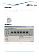
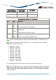
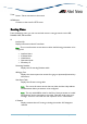
AT-9748TS/XP
(With 10G Uplink)
AT-9748TS/XP
(No Uplink)
AT-9724TS
0
1 <=11
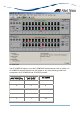
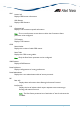
Device Manager LEDs for AT-9700 Series
LED State Description
PWR Green The switch is receiving power from the main power supply.
RPS Green
Gray
The switch is receiving power from the redundant power supply.
RPS is not installed or not functioning.
STACK ID Green
Orange
The stacked unit is either a slave switch or the switch is not in a
stacked mode.
The stacked unit is the master switch.
DUPLEX Green
Orange
The port is operating in full-duplex mode.
The port is operating in half-duplex mode.
Note - The Stack ID LED indicates the Box ID of the stacked switch or standalone switch.
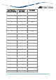
Note - When multiple units of the AT-9700 series are stacked together, port numbering
is continuous based on the Box ID.
• Box ID 1 - 1 to 64
• Box ID 2 - 65 to 128
• Box ID 3 - 129 to 192
• Box ID 4 - 193 to 256
• Box ID 5 - 257 to 320
• Box ID 6 - 321 to 384
• Box ID 7 - 385 to 448
• Box ID 8 - 449 to 512
• Box ID 9 - 513 to 576
• Box ID 10 - 577 to 640
• Box ID 11 - 641 to 704
• Box ID 12 - 705 to 768
This numbering scheme assumes that a unit can have a maximum of 64 ports.
Note - The current firmware version does not allow Device Manager to detect the presence
or absence of an SFP module in any of the SFP slots. As a result, the SFP slots on the device
image will always show SFP images regardless of whether or not SFP modules are physically
present in the slots.