AlliedView™-EMS 4.0.3 DEVICE MANAGEMENT GUIDE AlliedView™-EMS 4.0.
TABLE OF CONTENTS DEVICE MANAGEMENT GUIDE................................................................................................................................1 BASIC OPERATIONS ...................................................................................................................................................9 COMMON OPERATIONS ON THE MAIN WINDOW ....................................................................................................................
AT-8400..................................................................................................................................................................... 102 MAIN WINDOW ......................................................................................................................................................................102 AGENT MENU ..............................................................................................................................................
AT-AR410 ................................................................................................................................................................. 140 MAIN WINDOW ......................................................................................................................................................................140 AGENT MENU ................................................................................................................................................
AT-8800 SERIES........................................................................................................................................................ 188 MAIN WINDOW ......................................................................................................................................................................188 AGENT MENU ....................................................................................................................................................
AT-9400 SERIES........................................................................................................................................................ 257 MAIN WINDOW ......................................................................................................................................................................257 AGENT MENU ....................................................................................................................................................
AVAILABILITY MENU ................................................................................................................................................................358 RMON MENU..........................................................................................................................................................................358 PORT MENU .........................................................................................................................................
POWERBLADE......................................................................................................................................................... 453 MAIN WINDOW ......................................................................................................................................................................453 AGENT MENU .......................................................................................................................................................
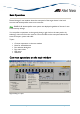
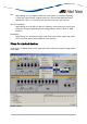
Basic Operations Device Manager's main window shows the main panel of the target device. It has both common and device-specific menus on its menu bar. Note - SNMPv3: All device-specific menu options are displayed regardless of the user's view access security settings. You can perform operations on the agent by doing a right click on the main panel or by selecting a menu item from the menu bar. Ports and LEDs on the main panel indicate the status of the port, system and traffic.
Port Right clicking on a port opens a pull-down menu specific to the device. Selecting a menu item opens another window and lets you view and edit MIB information related to the port. You can also access the same menu from the menu bar. RS-232 Terminal Port Right clicking on an RS-232 port opens a pull-down menu and lets you choose how to log into the agent. Depending on the managed device, choose Telnet or WEB Browser.
Port selection dialog box When you select a menu item acting on ports, a dialog box opens to let you select ports. Check the target ports and click OK. Note - If you select multiple ports, it may take some time for data to be displayed. Select Port dialog box Port status colors Port status is shown by its color. Port speed is also displayed in the port image.
Utilization Utilization is calculated by the following formula. # of frames x (96 + 64) + octets x 8 Utilization (%) = ------------------------------------------- x 100 Port speed (bps) x Sampling Interval(sec) Basic Operations AlliedView™-EMS 4.0.
AT-8000 Series This section describes Device Manager menus and operations specific to the AT-8000 Series. Topics: • • • • • • • Main Window Agent Menu Bridge Menu RMON Menu Port Menu Stacking Menu Expansion Module Notes Main Window AT-8012M AlliedView™-EMS 4.0.
AT-8012M-QS AT-8016F/MT AlliedView™-EMS 4.0.
AT-8016F/SC AT-8016F/ST AlliedView™-EMS 4.0.
AT-8024 AT-8024GB AlliedView™-EMS 4.0.
AT-8024M AT-8026FC AlliedView™-EMS 4.0.
AT-8026T AT-8088/MT AlliedView™-EMS 4.0.
AT-8088/SC Device Manager LEDs for AT-8000 Series LED State Description PWR Green The switch is receiving power. MASTER Orange Gray DUPLEX Green Orange The switch is the master switch of an enhanced stack. The switch is a slave switch or is not a member of an enhanced stack. The port is operating in full-duplex mode. The port is operating in half-duplex mode. Note - Please refer to Uplink Modules for the operations and behavior of the expansion modules installed on these devices.
Note - Setting the 'Active Protocol Version' to 'STP' and 'Spanning Tree Status' to 'enabled' will set the Port State parameter of disabled ports to 'blocking'. As a result, port images for disabled ports will turn yellow. Note - Setting the 'Active Protocol Version' to 'RSTP' and 'Spanning Tree Status' to 'enabled' will set the Port State parameter of inactive ports and disabled ports to 'blocking'. As a result, port images for inactive ports and disabled ports will turn yellow.
MAC Address Table Displays a list of static MAC addresses configured on the switch. Note - MAC Address Table entries created through a local or telnet management session will not be visible to Device Manager until the device is restarted. Reset Telnet Resets the switch. Starts a Telnet connection to the switch. WEB Browser Connects to the switch's HTTP server. Bridge Menu From the Bridge menu, you can view and edit bridge information such as the forwarding database and the spanning tree status.
RMON Menu From the RMON menu you can view and edit the RMON MIB. Statistics Displays traffic statistics in the network segment attached to each port. History Control Table Displays the RMON History table. Note - The current firmware version does not support the "historyControlTable" MIB object of RFC1757. As a result, Device Manager displays the error message "Failed to get MIB data." when the History Control Table option is selected from the RMON menu. Alarm Table Displays the RMON Alarm table.
Detail Info Displays detailed port information such as duplex mode. Note - Valid MIB Set values for the Port Flow Control parameter are 'disable', 'transmit-only', 'receive-only', and 'transmit-and-receive'.
Port Mirroring Displays port mirroring parameters and allows configuration of port mirroring state, source, and destination. Note - Valid MIB Set values for the Mirroring Destination Port parameter should range from 0 to 24. However, the current firmware version allows the user to enter values up to 65535. Attempting to enter values greater than 65535 will cause the new value to be converted to its equivalent wrap-around value; i.e., 65536 will become 0, 65537 will become 1, and so on.
Expansion Module Notes • Device Manager cannot distinguish between the AT-A45/xx, AT-A47, and AT-STACKM expansion modules. All are displayed with the same GIF image. • When both the AT-A45 and AT-A46 expansion modules are present on a device, the AT-A45 port image may show up as green and its Port Speed parameter may reflect the value "1 Gbps" even if there is no connection established on the port. To reflect the correct port image color and port speed, restart the device.
AT-8000/8POE This section describes Device Manager menus and operations specific to the AT-8000/8POE switch. Topics: • • • • • Main Window Agent Menu Bridge Menu RMON Menu Port Menu Main Window AT-8000/8POE LED State Device Manager LEDs for AT-8000/8POE Description PWR Green The switch is receiving power. DUPLEX Green The port is operating at full-duplex mode. Orange The port is operating at half-duplex mode.
Note - The current firmware version does not allow Device Manager to detect the presence or absence of an SFP module in the SFP slot. As a result, the SFP slot on the device image will always show an SFP image regardless of whether or not an SFP module is physically present in the slot. Note - Status information for port 9 will always be reflected on both the RJ-45 port image and the SFP port image regardless of whether it is the RJ-45 or the SFP port that is actually in operation.
Telnet Starts a Telnet connection to the switch. WEB Browser Connects to the switch's HTTP server. Bridge Menu From the Bridge menu, you can view and edit bridge information such as the spanning tree status. Forwarding Database Displays the Forwarding Database table as returned by the device. Discard/Aging Time Info Displays information about the device's aging time. Spanning Tree Info Displays spanning tree parameters such as priority and cost.
Note - To collect statistical data on an interface, do the following using a MIB browser tool that allows you to issue an SNMP Set request on a specific table element: Set the etherStatsStatus (1.3.6.1.2.1.16.1.1.1.21) object to "createRequest(2)" • Set the etherStatsDataSource (1.3.6.1.2.1.16.1.1.1.2) object to the OID of the Ethernet interface to monitor (e.g. 1.3.6.1.2.1.2.2.1.1.
Port Menu From the Port menu, you can view and edit MIB information about the port. Utilization Displays the port's utilization information. Interface Info Standard Displays port statistics such as the number of packets received and transmitted on the port, bytes received and transmitted on the port and port status. Note - The current firmware version returns a NULL value for the Specific Media MIB parameter.
Port Mirroring Displays port mirroring parameters and allows configuration of port mirroring state, source and destination. IGMP Snooping Displays the current state of IGMP Snooping and allows reconfiguration. AT-8000/8POE AlliedView™-EMS 4.0.
AT-8000GS Series This section describes Device Manager menus and operations specific to the AT-8000GS Series. Topics: • • • • • • • • • Main Window Agent Menu Routing Menu Bridge Menu IGMP Menu LLDP Menu Security Menu RMON Menu Port Menu AlliedView™-EMS 4.0.
Main Window AT-8000GS/24, AT-8000GS/24POE and AT-8000GS/48 The AT-8000GS/24, AT-8000GS/24POE and AT-8000GS/48 can be combined to form a single stack of up to 6 units. Device Manager LEDs for AT-8000GS Series LED State Description PWR Green The switch is receiving power. STACK ID Orange Gray Green The stacked unit is either the Stacking Master or the Backup Master. The switch is a set to standalone mode. AlliedView™-EMS 4.0.
Device Manager LEDs for AT-8000GS Series The stacked unit is a slave switch. DUPLEX Green The port is operating in full-duplex mode. Orange The port is operating in half-duplex mode. Note - When multiple units of the AT-8000GS series are stacked together, port numbering is continuous based on the Stack Number.
Device Info General Info Displays common management information. Active Software File Displays the currently available images on the flash. Image Files Info Displays information about the images on the flash including the image version. Software Packages Displays the device's software packages. Physical Description Module Info Displays module information for each unit in the system. Port Attributes Displays port information. Unit General Info Displays the device's software versions.
Note - The current firmware version does not return any value for the Serial Number parameter. Stacking Info Basic Info Displays the stacking information. Note - Stacked devices: The current firmware version does not allow the Stack Reload Unit parameter to be set to a non-existing Unit ID. Attempting to do so will result to an error. Note - The current firmware version does not allow the Stack Order Permutation parameter to be configured.
POE Config Displays POE device's configurations. Note - AT-8000GS/24POE: When multiple units of the AT-8000GS series are stacked together, the current firmware version does not allow the Maximum PSE Power parameter to be configured to 'none' if the Unit ID of the device is '3', '4', '5' or '6'. Socket Info Displays the sockets information which are currently open in the system. Management Info General Management Displays common management information.
Mid-level Management Alarm Options Displays information about alarm options. Note - The current firmware version does not allow the Row Status parameter to be configured. Attempting to configure this parameter to any valid value will result in the error "The error occurred with 'Set' operation. Error: gen Error.". MIB Tree Displays information about the device's MIB tree. Tuning Agent Diagnostics Displays diagnostic information about the agent.
SSH Tuning Displays the current number of the maximum number of authorized keys and its value after reset. Terminal Sessions Displays the current number of maximum sessions and its value after reset. DNS Client Tuning Displays the maximum values of the cache entries and the negative cache entries before and after reset. DHCP Snooping Tuning Displays the current maximum number of DHCP snooping entries.
CLI Info Displays information if the file is enabled or not. Note - The current firmware does not allow the Password parameter to be configured. LCLI Info Displays information about the device's Telnet sessions and SSH sessions if enabled or not. Note - Valid MIB Set values for the History Size and SSH History Size parameters should range from 10-206 and 10-210 respectively. However, the current firmware version allows the user to enter values up to 246.
Date and Time Time Synchronization Displays the configuration about the device's date/time and time zone. Note - Valid MIB Set values for the DST Offset parameter should range from 1-1440. However, the current firmware version allows the user to enter values outside of the valid range and negative values as well. Note - The current firmware version does not allow the DST Start and DST End parameters to be configured when the DST Mode is set to 'recurring' or 'date' value.
Event Log Displays information about events sent to the system log file. Error Log Displays information about errors registered to the system cache. Syslog Device Displays information about Syslog diagnostic messages. Note - The current firmware version does not allow the Syslog Device Control parameter to be configured. Syslog Collector Displays the information to generate Syslog messages to an aggregating agent or collector.
Note - The current firmware version does not allow the Mapping Type parameter to be configured. Attempting to configure this parameter from 'static' to 'dynamic' value will result in the error "The error occurred with 'Set' operation. Error. bad value.". Note - The current firmware version does not allow the Mapping Type parameter to be set to 'invalid' or 'other' as its values. Address Table Standard Displays the list of IP interfaces on the switch.
I/F Name-Address Translation Displays information about the IP interface's name translated to an IP interface address. TFTP Displays configuration information about the TFTP. Note - The current firmware version does not allow the Send Config File parameter to be configured. Note - Configuring the Get Config File parameter will cause the device to reboot and reset its running configuration to default configuration.
Note - The current firmware version does not allow the following parameters to be configured: • • • • • • Destination Port Number Routing Protocol MIB Destination Metric 2 Destination Metric 3 Destination Metric 4 Destination Metric 5 Note - The current firmware version only allows the Routing Type parameter to be set to 'reject' if the value prior to set operation is 'remote'. ICMP ICMP Statistics Displays ICMP Statistics.
Note - Configuring the Row Status parameter to invalid values will not return an error message except for the 'create and go' value. Enabled VLANs Displays the IP DHCP snooping enabled VLAN entries. Note - Configuring the Row Status parameter to invalid values will not return an error message except for the 'create and go' value. Trusted Ports Displays DHCP snooping configured as trusted ports.
Additional Counters Displays information about a collection of objects providing further instrumentation applicable to many but not all DNS resolvers. ISATAP Tunnel Info Displays the Intra-Site Automatic Tunnel Addressing Protocol tunneling info. Bridge Menu From the Bridge menu, you can view and edit bridge information such as the forwarding database and the spanning tree status. Forwarding Database Standard View Displays the Forwarding Database table as returned by the device.
Basic Bridge Info Displays basic bridge information. Bridge Port Info Displays statistics about frames received/transmitted on the switch port. Note - The current firmware version does not allow the Number of Traffic Class parameter to be configured. Attempting to configure this parameter to any valid value will result in the error "The error occurred with 'Set' operation. Error. bad value.". Note - The current firmware version returns the value 'NULL' for the Circuit parameter. 802.
IGMP Config Displays configurations of the Internet Group Management Protocol function. Note - Valid MIB Set values for the Host Aging Time parameter should range from 60 - 2147483647. However, the current firmware version allows the user to set values lower than 60. LLDP Menu From the LLDP menu, you can view and edit LLDP configurations, statistics, local system data and remote systems data components.
Port Rx Displays the LLDP frame reception statistics for a particular port. LLDP System Data Local System General Info Displays LLDP information associated with local systems. Port Info Displays port information associated with the local system. Management Addresses Displays the management address information on the local system. Note - The current firmware version returns the value 'NULL' for the OID parameter. Remote Systems Connection Info Displays one or more rows per physical network connection.
Note - Device Manager does not handle objects of type BITS correctly. As a result, the MED TLVs Tx Enable parameter will not be configurable and will display an 8-bit binary string instead of the actual TLV types allowed.
802.3 Config Port Config Displays the LLDP configuration information that controls the transmission of IEEE 802.3. Note - The current firmware version does not allow the 802.3 TLVs Tx Enable parameter to be configured. Note - Device Manager does not handle objects of type BITS correctly. As a result, the TLVs Tx Enable parameter will not be configurable and will display an 8-bit binary string instead of the actual TLV types allowed.
Note - The current firmware version accepts up to 160 characters for the System Password Level 1 to 15 parameters, including the '#' or '$' character as directive that indicates the type of password being used. However, using the '#' character will result to an error. Method Lists Displays information about all method lists. Note - The current firmware version does not allow the Row Status parameter to be set to 'create and go' or 'destroy' as its value.
Note - The current firmware version does not return any value for the Password Expiry Date parameter. Note - The current firmware version will always display an encrypted value for the Password parameter regardless of whether the type of password set is 'clear text' or 'encrypted password'. Note - Valid MIB Set values for the Password parameter should range from 1159 characters. However, the current firmware version allows the user to set values up to 160 characters.
Port-based Authentication Basic Info Displays basic port authentication and VLAN information. Note - Device Manager always treats objects of type OCTET STRING as a sequence of bytes in hexadecimal format and does not convert them to plain text format when necessary. As a result, the Guest VLAN Ports parameter will neither be readable nor configurable. Port Authentication Info Displays the value of the MAC based authentication information and Radius attributes.
Note - The current firmware version returns a 'noSuchName' value for the following parameters: • • • • Received Octets Transmitted Octets Received Frames Transmitted Frames Note - The current firmware version does not allow the Device Manager to display values for the User Name parameter. RADIUS Basic Info Displays basic RADIUS information. RADIUS Server Info Displays the IP address, UDP port number for authentication and accounting request, and current status of the RADIUS server.
TACACS+ Basic Info Displays basic TACACS+ information. TACACS+ Server Info Displays information about TACACS+ server. Note - Configuring the Row Status parameter to invalid values will not return an error message except for the 'create and go' value. Secure Shell SSH Server Displays information about the status of public key authentication and the type of regenerated host key.
Public Key Fingerprint Displays the fingerprint for the router's public key. Secure Socket Layer Basic Info Displays basic SSL information. Certificate Generation Displays information about the generated keys and self signed certificates.
RMON Menu From the RMON menu you can view and edit the RMON MIB. Statistics Displays traffic statistics in the network segment attached to each port. History Control Table Displays the RMON History table. Alarm Table Displays the RMON Alarm table. Event Table Displays the RMON Event table. Event Log Displays the RMON Event log. Port Menu From the Port menu, you can view and edit MIB information about the port. Utilization Displays the port's utilization information.
• • • • • • • Transmitted Buffer Length Received Unicast Packets (HC) Received Multicast Packets (HC) Received Broadcast Packets (HC) Transmitted Unicast Packets (HC) Transmitted Multicast Packets (HC) Transmitted Broadcast Packets (HC) Note - The current firmware version does not allow the Promiscuous Mode parameter to be set to 'false' as its value. Note - The current firmware version returns the value 'NULL' for the Specific Media MIB parameter.
Detail Info Displays detailed port information such as duplex mode. Note - The current firmware version does not allow the following parameters to be configured: • • • • • • Tagged Mode Default Priority Row Status Port Flow Control Config Port Speed Reactive and Combo Ethernet Config Attempting to configure these parameters to any valid value will result in the error "The error occurred with 'Set' operation. Error. bad value." except for the Default Priority parameter.
Spanning Tree Info STP Detail Info Displays the port's spanning tree parameters. Additional Info Displays a list of information maintained by every port about the Spanning Tree Protocol state for that port. Note - The current firmware version does not allow the Protocol Migration parameter to be set to 'true' as its value. MSTP MSTI CIST Displays a list of information maintained by every pair about the Spanning Tree Protocol state for that pair.
Note - The current firmware version returns a 'noSuchName' value for the Received Frames (HC) and Transmit Frames (HC) parameters. Note - The current firmware version does not allow the PAUSE Config parameter to be set to 'enabledXmit' or 'enabledRcv' as its value. Port Trunking Basic Info Displays basic information about port trunking. Note - The current firmware version does not allow the Trunk Creation Support and LACP Membership Restrictions Support parameters to be configured.
Storm Control Basic Info Displays basic information about storm control. Storm Control Protection Displays information about the storm control protection per port. Note - The current firmware version does not allow any of the parameters under this table to be configured except for the Broadcast Enable and Multicast Enable parameters. Storm Control Group Displays group identification for each supported frame type defined per port. AT-8000GS Series AlliedView™-EMS 4.0.
AT-8000S Series This section describes Device Manager menus and operations specific to the AT-8000S Series. Topics: • • • • • • • • • Main Window Agent Menu Routing Menu Bridge Menu IGMP Menu LLDP Menu Security Menu RMON Menu Port Menu Main Window AT-8000S/16 AlliedView™-EMS 4.0.
AT-8000S/24, AT-8000S/48 and POE Models The AT-8000S/24, AT-8000S/24POE, AT-8000S/48 and AT-8000S/48POE can be combined to form a single stack of up to 6 units. AlliedView™-EMS 4.0.
Device Manager LEDs for AT-8000S Series LED State Description PWR Green The switch is receiving power. STACK ID Orange Gray Green The stacked unit is either the Stacking Master or the Backup Master. The switch is a set to standalone mode. The stacked unit is a slave switch. DUPLEX Green The port is operating in full-duplex mode. Orange The port is operating in half-duplex mode.
Agent Menu From the Agent menu, you can view and edit the system information for the device, or log into the CLI using Telnet. System Info Displays basic system information, including system name, location, contact and description. Note - The current firmware version allows the System Name parameter to be set to 'NULL' and accepts inputs of up to 160 characters. Device Info General Info Displays common management information.
Note - The current firmware version allows the user to enter up to 160 characters for the Serial Number and Asset Tag parameters but values exceeding 19 characters will be truncated. Unit Environment Info Displays the device's main power supply and temperature status. Physical Entity Displays the information about the device including the serial number. Note - The current firmware version accepts up to 6 characters for the Physical Alias parameter.
POE Info Note - For devices configured in stacked mode, where at least one POE and one non-POE devices are members of the stack, attempting to access the POE Config table will cause the stacked devices to restart continuously unless the POE Config table is closed. MCU Info Displays POE device's Microcontroller information. POE Config Displays POE device's configurations. Socket Info Displays the sockets information which are currently open in the system.
Mid-level Management Alarm Options Displays information about alarm options. MIB Tree Displays information about the device's MIB tree. Tuning Agent Diagnostics Displays diagnostic information about the agent. Note - The current firmware version returns a 'noSuchName' value for the Location parameter. General Tuning Displays general tuning information. Note - The current firmware version accepts values in the range [0255] inclusive for the Debug Level parameter.
Management ACL Tuning Displays the current number of access rules and the number after reset. SSH Tuning Displays the current number of the maximum number of authorized keys and its value after reset. Terminal Sessions Displays the current number of maximum sessions and its value after reset. DNS Client Tuning Displays the maximum values of the cache entries and the negative cache entries before and after reset. DHCP Snooping Tuning Displays the current maximum number of DHCP snooping entries.
Telnet Sessions Displays the login time, client IP address and telnet session status. CLI Info Displays information if the file is enabled or not. LCLI Info Displays information about the device's Telnet sessions and SSH sessions if enabled or not. Note - Valid MIB Set values for History Size, Telnet History Size and SSH History Size parameters should range from 10 to 210. However, the current firmware version allows the user to enter values up to 246.
Date and Time Time Synchronization Displays the configuration about the device's date/time and time zone. Note - The current firmware version does not allow DST End and DST Start parameters to be configured. Note - Valid MIB Set values for the DST Offset parameter should range from 1 to 1440. However, the current firmware version allows the user to enter values in the range [-2147483648 to 2147483647] inclusive.
Event Log Displays information about events sent to the system log file. Error Log Displays information about errors registered to the system cache. Syslog Device Displays information about Syslog diagnostic messages. Note - Device Manager does not handle 8-bit string parameters correctly. As a result, the Syslog Device Control parameter will display the string "00000000" and will not be configurable. Syslog Collector Displays the information to generate Syslog messages to an aggregating agent or collector.
Additional Info Displays additional information about the address table. Note - The current firmware version does not allow the Port Number, Net Mask and IP Interface Owner parameters to be configured. Note - The Backup Address parameter is not applicable to the AT-8000S series and should be ignored. Static Route Table Displays the IP static routing table. Note - The current firmware version does not allow the Routing Type parameter to be set to 'local'.
UDP Statistics Displays UDP statistics. TCP Connection Info Displays TCP connection-specific information. Note - The current firmware version does not allow the Connection Status parameter to be configured. TCP Statistics Displays TCP statistics. CIDR Route Number Displays the number of valid CIDR entries. Route Table Displays the CIDR routing tables. Note - The current firmware version does not allow the Routing Type parameter to be set to 'local'.
Note - The current firmware version does not allow Host Name parameter to be configured. Note - The current firmware version does not allow Command Action parameter to be set to 'renew force auto config' as its value. DHCP Client Command Displays what DHCP action to apply. DHCP Relay Basic Info Displays basic DHCP relay information. Note - The current firmware version does not allow MIB Version parameter to be configured. DHCP Servers Displays the next DHCP configuration server.
DNS Resolver Resolver Config Displays information about the DNS client. Note - The current firmware version does not allow the Reset parameter to be set to "reset". Basic Counters Displays information about basic DNS counters. Counters by OpCode Displays information about the current count of resolver queries and answers. Counters by Response Code Displays information about the current count of responses to resolver queries.
Enhanced View Displays the Forwarding Database table on a per port basis. User can select a port or group of ports to view its corresponding Forwarding Database entries. Aging Time Info Displays information about the device's aging time. Spanning Tree Info STP Standard Displays the spanning tree information such as the STP version and path cost. Additional Info Displays additional STP information like supported type.
Port Priority Group Displays information about the port priority. Traffic Class Displays information about the traffic class and traffic class priority. Note - Valid MIB Set values for Traffic Class parameter are in the range [0-3] inclusive. Attempting to set this parameter to a value outside of the valid range will result in the error message: "The error occurred with 'Set' operation. Error: bad value." MAC Table Info Displays MAC table information.
Note - The current firmware version does not allow Port VLAN Tx Enable parameter to be set to 'true' as its value. Note - Device Manager does not handle objects of type BITS correctly. As a result, the TLVs Tx Enable parameter will not be configurable and will display an 8-bit binary string instead of the actual TLV types allowed.
Management Addresses Displays the management address information on the remote system learned on a particular port contained in the local chassis. Note - The current firmware version returns the value 'NULL' for the OID parameter. LLDP MED Device Info Displays information which describe the device's behavior of the LLDP-MED. MED Port Config Displays the LLDP configuration information that controls the transmission of the MED. Note - Device Manager does not handle objects of type BITS correctly.
Location Info Displays the Location information as advertised by the local system. Note - Device Manager always treats objects of type OCTET STRING as a sequence of bytes in hexadecimal format and does not convert them to plain text format when necessary. As a result, the Location parameter will neither be readable nor configurable. POE Info Displays the defined type of Power over Ethernet advertised by the local device.
Security Menu From the Security menu, you can view and edit different security and authentication protocols SSL, SSH, and port-based authentication. Authentication/Authorization/Accounting Basic Info Displays basic information about Authentication/Authorization/Accounting. Note - The current firmware version does not allow the EAP Current Method List parameter to be configured.
Local Users Displays information about all usernames, their passwords and their authorizations. Note - The current firmware version is unable to display any value for the Password Expiry Date parameter. Note - The current firmware version will always display an encrypted value for the User Password parameter regardless of whether the type of password set is 'clear text' or 'encrypted password'.
Port Session Authentication Info Displays the session statistics information for an Authenticator PAE. PAE Port Info Displays the system level information for each port supported by the Port Access Entity. Authenticator PAE Info Displays configuration objects for the Authenticator PAE associated with each port. Note - The current firmware version does not allow the Administrative Controlled Directions and Key Transmission Status parameters to be configured.
RADIUS Server Info Displays the IP address, UDP port number for authentication and accounting request, and current status of the RADIUS server. Note - The current firmware version does not allow the Usage parameter to be set to 'wireless authentication'. Authentication Client Info Displays the number of RADIUS Access-Response packets received from unknown addresses and the identifier of the RADIUS authentication client.
Note - Setting the Regenerate Self Key parameter to "rsa" or "dsa" will result in the error message: "The error occurred with 'Set' operation. Error: time out occurred". Connection with the AT-8000S device will be lost and the only way to re-establish connection will be to perform a manual reset. Note - The current firmware version does not allow the Regenerate Self Key parameter to be set to 'rsa1'. Note - The current firmware version accepts up to 160 characters for the User Name parameter.
RMON Menu From the RMON menu you can view and edit the RMON MIB. Statistics Displays traffic statistics in the network segment attached to each port. History Control Table Displays the RMON History table. Alarm Table Displays the RMON Alarm table. Event Table Displays the RMON Event table. Event Log Displays the RMON Event log. Port Menu From the Port menu, you can view and edit MIB information about the port. Utilization Displays the port's utilization information.
• • • • • • Received Unicast Packets (HC) Received Multicast Packets (HC) Received Broadcast Packets (HC) Transmitted Unicast Packets (HC) Transmitted Multicast Packets (HC) Transmitted Broadcast Packets (HC) Note - The current firmware version does not allow the Promiscuous Mode parameter to be configured. PHY Diagnostics Test Interface Displays entries containing objects for invoking tests on an interface. Note - The current firmware version does not allow Test Set Type parameter to be configured.
Note - The current firmware version does not allow the following parameters to be configured: • • • • • • Tagged Mode Default Priority Row Status Port Speed Reactivate Combo Ethernet Config Note - The current firmware version does not allow the Autonegotiation Capabilities Config parameter to be configured. Attempting to configure this parameter to any valid value will result in the error "The error occurred with 'Set' operation. Error: bad value.
Port Lock Basic Info Displays basic information about port lock. Interfaces Range Displays information about port lock interfaces range. MAC Control MAC Control Sublayer Displays information about the MAC Control sublayer on a single ethernetlike interface. Note - The current firmware version returns a 'noSuchName' value for the Unknown Opcodes Received and Unknown Opcodes Received (HC) parameters.
Aggregation Port Info Displays a list of Link Aggregation Control configuration parameters for each Aggregation Port on this device. Note - The current firmware version does not allow the Actor Administrative Key and Partner Administrative System ID parameters to be configured. Note - Device Manager does not handle 8-bit string parameters correctly. As a result, the Actor Administrative Status and Partner Administrative Status parameters will display unrecognizable values and will not be configurable.
AT-8300GB Series This section describes Device Manager menus and operations specific to the AT-8300GB Series. Topics: • • • • • • Main Window Agent Menu Bridge Menu RMON Menu Port Menu Stacking Menu AlliedView™-EMS 4.0.
Main Window AT-8326GB AlliedView™-EMS 4.0.
The AT-8326GB supports up to 6 AT-8326GB stacked switches or any of the following mixed stack combinations of AT-8326GB and AT-8350GB switches: • • • • Two AT-8326GB switches and one AT-8350GB switch Two AT-8326GB switches and two AT-8350GB switches Three AT-8326GB switches and one AT-8350GB switch Four AT-8326GB switches and one AT-8350GB switch Note - When 3 or more AT-8326GB devices are stacked together, expect the twisted pair port image of Port 26 on the last device on the stack to turn green.
Note - Status information for the gigabit ports will always be reflected on the RJ-45 gigabit port images regardless of whether the gigabit ports have been set to operate as GBIC ports or as Twisted Pair ports. Note - When Global STP is enabled, the current firmware version sets the Port State parameter of inactive ports to 'blocking'. As a result, expect port images for inactive ports to turn yellow in Device Manager .
Reset Resets the switch. Telnet Starts a Telnet connection to the switch. WEB Browser Connects to the switch's HTTP server. Bridge Menu From the Bridge menu, you can view and edit bridge information such as the forwarding database and the spanning tree status. Forwarding Database Standard View Displays the Forwarding Database table as returned by the device. Enhanced View Displays the Forwarding Database table on a per port basis.
Event Table Displays the RMON Event table. Event Log Displays the RMON Event log. Port Menu From the Port menu, you can view and edit MIB information about the port. Utilization Displays the port's utilization information. Interface Info Displays port statistics such as the number of frames received and transmitted on the port, bytes received and transmitted on the port, and port status. Note - Valid MIB Set values for the Administration Status parameter are 'up' and 'down'.
Spanning Tree Info Displays the port's spanning tree parameters. Enable Enables the port. Disable QoS Disables the port. Displays QoS parameters and allows enabling of QoS status and setting priority queue. Port Mirroring Displays port mirroring parameters and allows configuration of port mirroring state, source and destination. IGMP Snooping Displays the current state of IGMP Snooping and allows reconfiguration.
AT-8400 This section describes Device Manager menus and operations specific to the AT-8400 switch. Topics: • • • • • • Main Window Agent Menu Bridge Menu RMON Menu Port Menu Stacking Menu Main Window AT-8400 AlliedView™-EMS 4.0.
LED Device Manager LEDs for AT-8401 Management Module State Description FAN A Green FAN TRAY A is installed and is operating correctly. Gray FAN TRAY A is not installed. Green FAN TRAY B is installed and is operating correctly. Gray FAN TRAY B is not installed. Green The switch is the master of an enhanced stack. Gray The switch is either a slave switch of an enhanced stack or the switch is not a member of an enhanced stack.
Network Info Displays network-related information such as the addresses of the default gateway and the agents. Note - The current firmware version does not allow the DNS Server and Default Domain Name parameters to be configured. Attempting to configure these parameters will result in the error message: "The error occurred with 'Set' operation. Error: gen Error.". Chassis Info Displays chassis information including the firmware information.
Note - It may take some time to retrieve Forwarding Database information. As a result, some Forwarding Database parameters may not show any value. To avoid this, click on File > Property > Polling options and set the Polling Interval parameter to 25 seconds or longer. Discard/Aging Time Info Displays information about the number of address entries that were learned but discarded because either there was a lack of memory or the entry's aging timer expired.
Event Log Displays the RMON Event log. Port Menu From the Port menu, you can view and edit MIB information about the port. Note - Ports are numbered continuously from top to bottom, across all installed line cards, starting from the leftmost line card all the way through the rightmost line card. This applies to the following submenu options: • • • • Utilization Interface Info -> Standard Error Statistics -> Standard Spanning Tree Info Utilization Displays the port's utilization information.
Enable Enables the port. Disable Disables the port. Port Mirroring Displays port mirroring parameters and allows configuration of port mirroring state and port's source list. Note - Valid MIB Set values for the Port Mirroring Configuration Entry Status parameter are 'active', 'not in service' and 'destroy'. Attempting to set this parameter to any other value will result in the error message: "The error occurred with 'Set' operation. Error: bad value.".
AT-8400 Line Cards This section describes the AT-8400 Line Cards supported by Device Manager. If line cards are installed on the AT-8400 chassis at the time Device Manager is called, they will be displayed in their corresponding slots on the chassis image. • • • • AT-8411 AT-8412 AT-8413 AT-8414 AT-8411 AT-8411 LED State Description DUPLEX Green The port is operating in full-duplex. Orange The port is operating in half-duplex.
AT-8412 AT-8412/MT AT-8412/SC LED State Description DUPLEX Green The port is operating in full-duplex. Note - The current firmware version does not allow the Port Flow Control parameter of ports on the AT-8412/MT and AT-8412/SC line cards to be set to 'auto'. Attempting to set this parameter to 'auto' will result in the error message: "The error occurred with 'Set' operation. Error: gen Error". AT-8413 AT-8413GB/T AlliedView™-EMS 4.0.
LED State Description DUPLEX Green The port is operating in full-duplex. Orange The port is operating in half-duplex. Note - A GBIC image is always visible on the GBIC slot of the AT-8413GB/T line card image even if there is no GBIC physically present in the slot. Note - Status information for the AT-8413GB/T ports will always be reflected on the RJ-45 port image regardless of whether the port that is in actual use is the GBIC port or the twisted pair port.
AT-9000/24 This section describes Device Manager menus and operations specific to the AT-9000/24 switch. Topics: • • • • • Main Window Agent Menu Bridge Menu RMON Menu Port Menu Main Window AT-9000/24 Device Manager LEDs for AT-9000/24 Description LED State PWR Green The switch is receiving power. DUPLEX Green The port is operating at full-duplex mode. Orange The port is operating at half-duplex mode. Note - Disabled ports will not turn red.
Note - Status information for ports 21 to 24 will always be reflected on both the RJ-45 port images and the SFP port images regardless of whether it is the RJ-45 or the SFP ports that are actually in operation. However, if Device Manager detects that the established link speed is less than 1Gbps, only the RJ-45 port images will turn green. Note - When Global RSTP is enabled, the current firmware version sets the Port State parameter of inactive ports to 'blocking'.
WEB Browser Connects to the switch's HTTP server. Bridge Menu From the Bridge menu, you can view and edit bridge information such as the spanning tree status. Bridge Info General Displays basic bridge information such as the LAN ID, bridge address, number of ports and the bridge type. Port Displays basic bridge information on a per port basis such as the LAN ID, port number, circuit, delay exceeded discards and MTU exceeded discards.
Error Displays error statistics in the network segment such as CRC errors, alignment errors, bad frames received late collisions and total transmit errors. Note - There may be times when Device Manager will not be able to successfully retrieve error statistical information. When this happens, all parameters in this table will display the value "retry over occurred". To prevent this from happening, do the following: • • • Go to File Property. Click on the Settings button in the Polling Options area.
Additional Info Displays port statistics such as the number of frames received and transmitted on the port, bytes received and transmitted on the port and port status. Error Statistics Displays error statistics. Detail Info Displays detailed port information such as duplex mode. Note - The Port State parameter always returns the value 'enabled' even if the physical port is actually disabled.
AT-9000/xx Series This section describes Device Manager menus and operations specific to the AT-9000/xx Series. Topics: • • • • • Main Window Agent Menu Routing Menu Bridge Menu Port Menu Main Window AT-9000/28 AlliedView™-EMS 4.0.
AT-9000/28SP AT-9000/52 Device Manager LEDs for AT-9000/xx Series LED States Description PWR Green The switch is receiving power. DUPLEX Green The port is operating in full-duplex mode. Orange The port is operating in half-duplex mode. AlliedView™-EMS 4.0.
Note - The current firmware version does not allow Device Manager to detect the presence or absence of an SFP module in any of the SFP slots. As a result, the SFP slots on the device image will always show SFP images regardless of whether or not SFP modules are physically present in the slots. Note - The current firmware version does not allow Device Manager to determine the actual duplex mode of the ports. As a result, the Duplex LED image is always GRAY regardless of an active connection.
Telnet Starts a Telnet connection to the switch. WEB Browser Connects to the switch's HTTP server. Routing Menu From the Routing menu, you can view and edit information about the switch's routing functions. IP ARP Table Displays the ARP cache on the switch . Note - The current firmware version does not allow the Physical Address and Mapping Type parameters to be configured. Address Table Displays the list of the IP interfaces on the switch.
Note - The current firmware version returns the value 'NULL' for the Routing Protocol MIB parameter. UDP Displays UDP listener information. TCP Displays TCP connection-specific information. Note - The current firmware version does not allow the Connection Status parameter to be configured. ICMP Statistics Displays ICMP Statistics. Bridge Menu From the Bridge menu, you can view and edit bridge information such as the forwarding database and the spanning tree status.
Bridge Port Info Displays statistics about frames received/transmitted on the switch port. Note - The current firmware version returns the value 'NULL' for the Circuit parameter. Port Menu From the Port menu, you can view and edit MIB information about the port. Interface Info Displays port statistics such as the number of packets received and transmitted on the port, bytes received and transmitted on the port and port status.
Spanning Tree Info Displays the port's spanning tree parameters. Note - The current firmware version returns a 'noSuchName' value for the Path Cost Contribution parameter. Note - Valid MIB Set values for the Port Path Cost parameter is in the range [1-65535] inclusive. However, the application allows it to be configured up to the value of 200000000.
AT-9006 Family This section describes Device Manager menus and operations specific to the AT-9006SX/SC and AT-9006T switches. Topics: • • • • • • Main Window Agent Menu Bridge Menu RMON Menu VLAN Menu Port Menu Main Window AT-9006SX/SC AlliedView™-EMS 4.0.
AT-9006T Device Manager LEDs for AT-9006 Family LED State Description PWR Green The switch is receiving power. RPS Green An optional redundant power supply is connected to the switch. Gray There is no redundant power supply connected to the switch. DUPLEX Green Orange The port is operating in full-duplex mode. The port is operating in half-duplex mode. Note - Ports on the expansion modules are numbered starting from 7.
Network Info Displays network-related information such as agent's and default gateway address. Manager Address Info Displays management station's IP address. Reset Telnet Reset the switch. Connect to the switch's telnet service. Bridge Menu From the Bridge menu, you can view and edit information such as forwarding database and spanning tree status. Forwarding Database Displays forwarding database table.
Event Table Displays RMON Event table. Event Log Displays RMON Event log. VLAN Menu From the VLAN menu, you can view the list of VLAN and member ports. Note - You cannot modify VLAN configuration on the AT-9006 Family using the VLAN menu. Name List Displays configured VLAN names. Port Info Displays VLAN to which the port belongs. Port Menu From the Port menu, you can view and edit MIB information about the port. Utilization Displays port's utilization information.
AT-9410GB This section describes Device Manager menus and operations specific to the AT-9410GB switch. Topics: • • • • • Main Window Agent Menu Bridge Menu RMON Menu Port Menu Main Window AT-9410GB Device Manager LEDs for AT-9410GB Description LED State PWR Green The switch is receiving power. DUPLEX Green The port is operating at full-duplex mode. Orange The port is operating at half-duplex mode.
Note - When a port on the AT-9410GB is set to 'auto sense' and is connected to a halfduplex port on another device, its corresponding Duplex LED on the device image turns green instead of orange. Note - A GBIC image is always visible on each of the GBIC slots of the device image even if there are no GBICs physically inserted. Agent Menu From the Agent menu, you can view and edit the system information for the device, or log into the CLI using Telnet.
Reset Resets the switch. Telnet Starts a Telnet connection to the switch. WEB Browser Connects to the switch's HTTP server. Bridge Menu From the Bridge menu, you can view and edit bridge information such as the forwarding database and the spanning tree status. Bridge Info Displays basic bridge information such as the LAN ID, bridge address, number of ports and the bridge type. Forwarding Database Displays the Forwarding Database table.
Event Table Displays the RMON Event table. Event Log Displays the RMON Event log. Port Menu From the Port menu, you can view and edit MIB information about the port. Utilization Displays the port's utilization information. Interface Info Displays port statistics such as the number of frames received and transmitted on the port, bytes received and transmitted on the port, and port status. Note - Valid MIB Set values for the Administration Status parameter are 'up' and 'down'.
Note - Valid MIB Set values for the Port State parameter are 'enabled' and 'disabled'. Attempting to set this parameter to any other value will result in the error message: "The error occurred with 'Set' operation. Error: bad value." Spanning Tree Info Displays the port's spanning tree parameters. Enable Enables the port. Disable Disables the port. QoS Displays QoS parameters and allows enabling of QoS status and setting priority queue.
AT-AR400S Series This section describes Device Manager menus and operations specific to the AT-AR400S Series. Topics: • • • • • • • • Main Window Agent Menu Routing Menu Bridge Menu ATM Menu (not applicable to the AT-AR450S) ADSL Menu (AT-AR440S and AT-AR441S only) SHDSL Menu (AT-AR442S only) Port Menu Main Window AT-AR415S AlliedView™-EMS 4.0.
AT-AR440S AT-AR441S AlliedView™-EMS 4.0.
AT-AR442S AT-AR450S Device Manager LEDs for AT-AR400S Series Description LED State PWR Green The router is receiving power. DUPLEX Green The port is operating at full-duplex. Gray The port is either inactive or is operating at half-duplex. Green The interface is enabled and the link is up. Orange The interface is enabled and is handshaking. The interface is enabled and is training to negotiate the link. ADSL AlliedView™-EMS 4.0.
Black Red Device Manager LEDs for AT-AR400S Series The interface is enabled and the link is down. The interface is disabled. Note - Please refer to Port Interface Cards (PICs) for the operations and behavior of the Port Interface Cards installed in these devices. Agent Menu From the Agent menu, you can view and edit the system information for the router, or log into the CLI using Telnet. System Info Displays basic system information, including system name, location, contact and description.
Route Table Displays the IP routing table on the router. IP Statistics Displays statistics about IP routing, including the number of IP datagrams received. ICMP Statistics Displays ICMP statistics. Bridge Menu From the Bridge menu, you can view and edit bridge information such as the forwarding database and spanning tree status. The Bridge submenus are greyed out if bridges not configured.
Channel Configuration Displays ATM Channel configuration information. Note - The current firmware version does not allow the following parameters to be configured: • • Receive Traffic Descriptor Index Transmit Traffic Descriptor Index Attempting to configure these parameters will result in the error message: "The error occurred with 'Set' operation. Error: noSuchName." Channel Error Statistics Displays information about errors related to ATM channels.
Line Configuration Displays span configuration profiles for SHDSL lines. Alarm Configuration Displays alarm configuration profiles for HDSL2/SHDSL segment endpoints. Port Menu From the Port menu, you can view and edit MIB information about selected ports. Utilization Displays the port's utilization information. Note - Utilization menu does not apply for AT-AR450S devices.
AT-AR410 This section describes Device Manager menus and operations specific to the AT-AR410 router. Topics: • • • • • • • Main Window Agent Menu Routing Menu Bridge Menu Frame Relay Menu Call List Menu Port Menu Main Window AT-AR410 with PIC installed LED State Device Manager LEDs for AT-AR410 Description PWR Green The router is receiving power. DUPLEX Green The port is operating at full-duplex. Gray The port is either inactive or is operating at half-duplex.
Agent Menu From the Agent menu, you can view and edit the system information for the router, or log into the CLI using Telnet. System Info Displays basic system information, including system name, location, contact and description. File List Displays a list of the files in the router's flash and NVS file systems. Config File Name Displays the file name of the start-up configuration file. Telnet Starts a Telnet connection to the router.
Bridge Menu From the Bridge menu, you can view and edit bridge information such as the forwarding database and spanning tree status. The Bridge submenus are greyed out if bridges not configured. Discard/Aging Time Info Displays information about the number of address entries that were learned but discarded because either there was a lack of memory or the entry's aging timer expired. Spanning Tree Info Displays spanning tree parameters such as priority and cost.
Port Menu From the Port menu, you can view and edit MIB information about selected ports. Interface Info Displays port statistics such as the number of frames received and transmitted on the port, bytes received and transmitted on the port, and port status. Spanning Tree Info Displays the port's spanning tree parameters. AT-AR410 AlliedView™-EMS 4.0.
AT-AR700 Series This section describes Device Manager menus and operations specific to the AT-AR700 Series. Topics: • • • • • • • Main Window Agent Menu Routing Menu Bridge Menu Frame Relay Menu Call List Menu Port Menu Main Window AT-AR745 AlliedView™-EMS 4.0.
AT-AR745-DC Device Manager LEDs for AT-AR700 Series Description LED State PWR Green The router is receiving power from the main power supply unit. Red The main PSU has failed. Green The router is receiving power from the redundant power supply. Red RPS has failed. Gray RPS is not installed or RPS monitoring is disabled. Green The port is operating at full-duplex.
Note - To turn RPS monitoring on or off on the router, enter the command SET SYSTEM RPSMONITOR={ON|OFF} from the command line interface. To see whether RPS monitoring is on, use the command SHOW SYSTEM. To turn on RPS monitoring using SNMP, set the fanAndPsRpsMonitoringStatus variable to on. Note - The current fimware version does not allow Device Manager to support the RPS LED on the DC models.
IP Statistics Displays statistics about IP routing, including the number of IP datagrams received. ICMP Statistics Displays ICMP statistics. Bridge Menu From the Bridge menu, you can view and edit bridge information such as the forwarding database and spanning tree status. The Bridge submenus are greyed out if bridges are not configured.
Port Menu From the Port menu, you can view and edit MIB information about selected ports. Interface Info Displays port statistics such as the number of frames received and transmitted on the port, bytes received and transmitted on the port, and port status. Error Statistics Displays error statistics for the port. Spanning Tree Info Displays the port's spanning tree parameters. This option is greyed out if bridge ports are not configured on the router at the time Device Manager is started.
AT-AR700S Series This section describes Device Manager menus and operations specific to the AT-AR700S Series routers. Topics: • • • • • • • • Main Window Agent Menu Routing Menu LAN/WAN Menu Availability Menu Security Menu RMON Menu Port Menu Main Window AT-AR750S AlliedView™-EMS 4.0.
AT-AR750S-DP AT-AR770S Note - AT-AR770S: DUP LEDs of active ports will always be orange regardless of the actual duplex mode of the ports. This is because the current firmware version always returns a half-duplex value for the Duplex Mode parameter of these ports. Device Manager LEDs for the AT-AR700S Series Description LED State PWR Green The router is receiving power from the main power supply unit. DUPLEX Green The port is operating at full-duplex.
Note - Please refer to Port Interface Cards (PICs) for the operations and behavior of the Port Interface Cards installed on these devices. Agent Menu From the Agent menu, you can view and edit the system information for the router, or log into the CLI using Telnet. System Info Standard Displays basic system information, including system name, location, contact and description. Enterprise CPU Utilization Displays information about the CPU utilization over different periods of time.
Hardware Info Total Boards Displays the number of boards that are currently installed. Board Info Displays basic information on the boards that are currently installed. Slot Info Displays information on the Power Supply Bay slots. Physical Interfaces Displays information about the interfaces found in the device. Firmware Info Install Configurations Displays information about the Software release currently loaded in the device.
Loader Load Status Displays the status of the device loader. Load Parameters Displays information about the files to be loaded. LLDP Configuration General Config Displays basic LLDP configuration. Port Config Displays LLDP configuration for each port. Note - The current firmware version returns a 'noSuchName' value for the Port Number parameter. Note - Device Manager does not handle objects of type BITS correctly.
Local System Data General Info Displays information about the local LLDP system. Port Info Displays information on the LLDP of local ports. Note - The current firmware version returns a 'noSuchName' value for the Port Number parameter. Management Addresses Displays management addresses of the local LLDP system. Note - The current firmware version returns the value 'NULL' for the OID parameter. Reset Cold Initiates a cold restart on the switch. Reset Warm Initiates a warm restart on the switch.
Route Table Displays the IP routing table on the switch. Note - The current firmware version returns the value 'NULL' for the Routing Protocol MIB parameter. Note - The following parameters are implemented as 'read-only': • • • • • • • • • Destination Port Number Routing Type Next Hop AS Number Destination Metric 1 Destination Metric 2 Destination Metric 3 Destination Metric 4 Destination Metric 5 Row Status IP Statistics Displays statistics about IP, such as the number of IP datagrams received.
BGP General Info Displays information about the BGP module. Peer Info Displays BGP Peer information. Note - The current firmware version does not allow the following parameters to be configured: • • • • • Connect Retry Interval Configured Hold Time Configured Keep Alive Min AS Origination Interval Min Route Advertisement Interval Path Attributes Displays the BGP path attributes.
ISDN Call Details Displays ISDN call information such as ISDN number and call direction for active calls. Note - The Remote Call parameter does not allow input values that contain hyphens. Note - If the In CLI (Calling Line Info) Search parameter is set to 'list', the In CLI (Calling Line Info) List Check parameter gives the index of the CLI list to search. The value of CLI list indices ranges from 1 to 100. The value 0 is returned if the In CLI (Calling Line Info) Search parameter is not set to 'list'.
Call Detail Attachments Displays call detail attachment information. B Channel Attachments Displays B Channel attachment information. BRI Interfaces Displays BRI interface information. BRI Channels Displays BRI channels information. PRI Interfaces Displays PRI interface information. PRI Channels Displays PRI channels information. Frame Relay DLC Management Interfaces Displays DLCMI (Data Link Connection Management Interface) information.
• • • • Received DEs Sent DEs Logical Interface Index Row Status Note - The following parameters are implemented as 'read-only': • • • • Errors State CIR Maximum Line Speed Throughput Displays information about errors related to the Frame Relay module. Note - The Faults and Fault Time parameters are not applicable to the ATAR700S series and should be ignored. DS1 DS1 Config Displays DS1 configuration. Note - The current firmware version returns a 'noSuchName' value for the Port Number parameter.
Cumulative Statistics Displays accumulated near-end DS1 statistics. Far-End Current 15-Min Interval Statistics Displays far-end DS1 statistics every 15 minutes. Statistics for Past 24 Hours Displays far-end DS1 statistics for the past 24 hours. Cumulative Statistics Displays accumulated far-end DS1 statistics. Availability Menu From the Availability menu you can view and edit Server Load Balancing and Ping Polling information.
Note - Valid MIB Set values for the Number of Packets parameter should range from 0-4294967595. However, the current firmware version allows the user to enter negative values as well. Furthermore, attempting to set the parameter to 0 will result in the error message: "The error occurred with 'Set' operation. Error: bad value." Note - The current firmware version accepts values in the range [0-4294967595] inclusive for the Number of Packets and Time Interval parameters.
Enterprise Displays enterprise PAE port information. Note - Device Manager does not handle objects of type BITS correctly. As a result, the Capabilities parameter will display an 8-bit binary string instead of the actual PAE functionality supported. However, the PAE functionality supported can still be determined by looking at the bits that are on from right to left: • Bit 0 - Authenticator • Bit 1 - Supplicant Authenticator PAE Info Standard Displays standard authenticator PAE information.
MAC-based Authentication PAE Port Info Displays PAE port information. Note - The Initialize parameter is implemented as 'read-only'. Authenticator PAE Info Displays authenticator PAE information. Firewall Session Statistics Displays the statistics for the firewall sessions. RMON Menu From the RMON menu you can view and edit the RMON MIB. Statistics Displays traffic statistics in the network segment attached to each port. History Control Table Displays the RMON History table.
Note - Valid MIB Set values for the Administration Status parameter are 'up' and 'down' only. Note - The Promiscuous Mode parameter is implemented as 'read-only'. Detail Info Displays detailed port information such as duplex mode. Note - AT-AR770S: The current firmware version always returns 'half-duplex' for the Duplex Mode parameter regardless of the actual duplex mode of the port. Error Statistics Displays error statistics.
Enable Enables the port. Disable Disables the port. AT-AR700S Series AlliedView™-EMS 4.0.
AT-8500 Series This section describes Device Manager menus and operations specific to the AT-8500 Series. Topics: • • • • • • • • Main Window Agent Menu Routing Menu Bridge Menu RMON Menu Port Menu Stacking Menu Expansion Module Notes Main Window AT-8516F/SC AlliedView™-EMS 4.0.
AT-8524M AT-8524POE AlliedView™-EMS 4.0.
AT-8550GB AT-8550SP Device Manager LEDs for AT-8500 Series LED State Description PWR Green The switch is receiving power. MASTER Orange The switch is the master switch of an enhanced stack. Gray The switch is a slave switch or is not a member of an enhanced stack. Green The port is operating in full-duplex mode. Orange The port is operating in half-duplex mode. DUPLEX AlliedView™-EMS 4.0.
Device Manager LEDs for AT-8500 Series RPS Green Gray Yellow An optional redundant power supply is connected to the switch and is turned on. There is no redundant power supply connected to the switch. An optional redundant power supply is connected to the switch but is turned off. Note - Please refer to Uplink Modules for the operations and behaviour of the expansion modules installed on these devices.
Network Info Displays network-related information such as the addresses of the default gateway and the agents. Note - The current firmware version returns an initial value of '???(0)' for the Action parameter. Note - Valid MIB Set values for the Action parameter are 'reset' and 'defaultConfig'. The 'saveConfig' value is nonfunctional in the current firmware release and selecting it may cause the SNMP client on the device to stop responding to SNMP commands.
Routing Menu From the Routing menu, you can view and edit information about the switch's routing functions. IP ARP Table Displays the ARP cache on the switch. Address Table Displays the list of IP interfaces on the switch. Route Table Displays the IP routing table on the switch. IP Statistics Displays statistics about IP routing, including the number of IP datagrams received. Note - The current firmware version does not allow the Default TTL parameter to be configured.
Bridge Menu From the Bridge menu, you can view and edit bridge information such as the forwarding database and the spanning tree status. Forwarding Database Note - Changes to the Forwarding Database table caused by dynamic network topology/configuration changes will not be reflected unless the device is restarted. Standard View Displays the Forwarding Database table as returned by the device. Enhanced View Displays the Forwarding Database table on a per port basis.
Alarm Table Displays the RMON Alarm table. Event Table Displays the RMON Event table. Event Log Displays the RMON Event log. Port Menu From the Port menu, you can view and edit MIB information about the port. Utilization Displays the port's utilization information. Interface Info Standard Displays port statistics such as the number of packets received and transmitted on the port, bytes received and transmitted on the port and port status.
Detail Info Displays detailed port information such as duplex mode. Note - Valid MIB Set values for the Port Flow Control parameter are 'disable' and 'enable'. Attempting to set Port Flow Control to 'unknown' will cause the parameter to be set to 'enable'. Note - Valid MIB Set values for the Port Back Pressure parameter are 'disable' and 'enable'. Attempting to set Port Back Pressure to 'unknown' will cause the parameter to be set to 'enable'.
QoS Displays Quality of Service parameters and allows you to configure Flow Groups, Traffic Classes, and Policies. Flow Groups Displays Flow Group parameters used to group similar traffic flows together. Note - The current firmware version accepts up to 32 characters for the Description parameter. NULL values are not allowed. Traffic Classes Displays Traffic Class parameters used to provide most of the QoS controls.
Note - The current firmware version does not allow the Mirroring Source Port (Ingress) and Mirroring Source Port (Egress) parameters to be set to NULL. Note - The current firmware version does not allow the Port Mirroring Status parameter to be set to 'enabled' if, upon device startup, the Port Mirroring feature is disabled. MAC Address Security Displays MAC Address Security parameters and allows you to set the security level for dynamic and static MAC addresses learned and assigned to a port.
Expansion Module Notes • When adding/removing/changing an expansion module, Device Manager does not automatically refresh the device image in the main window to reflect the addition/removal/change. To view the updated device image, click on the Refresh option under the Agent menu. • The Port Speed and Mode parameter of the 100Base-FX port on the AT-A45/SC, AT-A45/SC-SM15 and AT-A45/MT expansion modules can only be set to '100Mbps full-duplex'.
AT-8700XL Series This section describes Device Manager menus and operations specific to the AT-8700XL Series of Advanced Layer 2 Switches. Topics: • • • • • Main Window Agent Menu Routing Menu Bridge Menu Port Menu Main Window AT-8724XL AlliedView™-EMS 4.0.
AT-8748XL LED Device Manager LEDs for AT-8700XL Series (AC Models) State Description PWR Green The switch is receiving power from the main power supply. Red Main power supply is either off or has failed. Green The switch is receiving power from the redundant power supply. Red RPS has failed. Gray RPS is not installed or RPS monitoring is disabled. Green The port is operating at full duplex. Orange The port is operating at half duplex.
Note - Please refer to Uplink Modules for the operations and behavior of the uplink modules installed on these devices. Note - To turn RPS monitoring on or off on the switch, enter the command SET SYSTEM RPSMONITOR={ON|OFF} from the command line interface. To see whether RPS monitoring is on, use the command SHOW SYSTEM. To turn on RPS monitoring using SNMP, set the fanAndPsRpsMonitoringStatus variable to on. Note - The current firmware version does not allow Device Manager to support the Reset button.
Routing Menu From the Routing menu, you can view and edit information about the switch's IP routing functions. ARP Table Displays the mapping of IP addresses to MAC addresses (the ARP cache), on the switch. Address Table Displays the list of IP interfaces and their IP addresses on the switch. Route Table Displays the IP routing table on the switch. IP Statistics Displays statistics about IP routing, including the number of IP datagrams received.
Port Menu From the Port menu, you can view and edit MIB information about the port. Utilization Displays the port's utilization information. Interface Info Displays port statistics such as the number of frames received and transmitted on the port, bytes received and transmitted on the port, and port status. Error Statistics Displays error statistics. Spanning Tree Info Displays the port's spanning tree parameters. Enable Disable Enables the port. Disables the port. AT-8700XL Series AlliedView™-EMS 4.0.
AT-8600 Series This section describes Device Manager menus and operations specific to the AT-8600 Series Layer 3 Switch. Topics: • • • • • • Main Window Agent Menu Routing Menu Bridge Menu Port Menu Expansion Module Notes Main Window AT-8624POE AlliedView™-EMS 4.0.
AT-8624T/2M AT-8648T/2SP Device Manager LEDs for AT-8600 Series Description LED State PWR Green The switch is receiving power from the main power supply. Red Main power supply is either off or has failed. Green The switch is receiving power from the redundant power supply. Red RPS has failed. RPS AlliedView™-EMS 4.0.
Gray DUPLEX Device Manager LEDs for AT-8600 Series RPS is not installed or RPS monitoring is disabled. Green The port is operating at full duplex. Orange The port is operating at half duplex. Note - At device start-up, the current firmware version returns 'operational' status for all ports. As a result, RJ-45 SFP port image will appear on ports 49-50 even if there is no SFP module inserted. Note - The current firmware version does not allow Device Manager to support the Reset button.
Routing Menu From the Routing menu, you can view and edit information about the switch's IP routing functions. ARP Table Displays the mapping of IP addresses to MAC addresses (the ARP cache), on the switch. Address Table Displays the list of IP interfaces and their IP addresses on the switch. Route Table Displays the IP routing table on the switch. IP Statistics Displays statistics about IP routing, including the number of IP datagrams received.
Port Menu From the Port menu, you can view and edit MIB information about the port. Utilization Displays the port's utilization information. Interface Info Displays port statistics such as the number of frames received and transmitted on the port, bytes received and transmitted on the port, and port status. Error Statistics Displays error statistics. Spanning Tree Info Displays the port's spanning tree parameters. MAU Info Displays interface-related MAU information for the port.
AT-8800 Series This section describes Device Manager menus and operations specific to the AT-8800 Series of Intelligent Workgroup Switches. Topics: • • • • • Main Window Agent Menu Routing Menu Bridge Menu Port Menu Main Window AT-8824 AlliedView™-EMS 4.0.
AT-8848 Device Manager LEDs for AT-8800 Series Description LED State PWR Green The switch is receiving power from the main power supply. Red Main power supply is either off or has failed. Green The switch is receiving power from the redundant power supply. Red RPS has failed. Gray RPS is not installed or RPS monitoring is disabled. Green The port is operating at full duplex. Orange The port is operating at half duplex. Grey There is no link over the port.
Agent Menu From the Agent menu, you can view and edit the system information for the switch, or log into the CLI using Telnet. System Info Displays basic system information, including system name, location, contact and description. Firmware Info Displays a list of software releases installed on the switch. Power Supply Info Displays information about the power supply, redundant power supply and power supply monitoring. File List Displays a list of the files in the switch's file system.
Routing Menu From the Routing menu, you can view and edit information about the switch's IP routing functions. ARP Table Displays the ARP cache on the switch. Address Table Displays the list of IP interfaces on the switch. Route Table Displays the IP routing table on the switch. IP Statistics Displays statistics about IP, such as the number of IP datagrams received. ICMP Statistics Displays statistics about ICMP, such as the number of ICMP datagrams received.
Port Menu From the Port menu, you can view and edit MIB information about the port. Utilization Displays the port's utilization information. Interface Info Displays port statistics such as the number of frames received and transmitted on the port, bytes received and transmitted on the port, and port status. Error Statistics Displays error statistics. Spanning Tree Info Displays the port's spanning tree parameters. MAU Info Displays interface-related MAU information for the port.
AT-8948 This section describes Device Manager menus and operations specific to the AT-8948 Enhanced Layer 3+ Switch. Topics: • • • • • • • • • Main Window Agent Menu Routing Menu Bridge Menu LLDP Menu Availability Menu Security Menu RMON Menu Port Menu Main Window AT-8948 LED State Device Manager LEDs for the AT-8948 Description PWR 1 and Green PWR 2 Gray There is a power supply unit (PSU) in the PSU bay. FAN There is a functioning Fan Only Module (FOM) in the PSU bay.
DUPLEX Gray Device Manager LEDs for the AT-8948 There is no functioning Fan Only Module (FOM) in the PSU bay. Green The port is operating at full duplex. Orange The port is operating at half duplex. Note - The current firmware version does not allow Device Manager to display the correct image for SFP module 'AT-SPFXBD-LC-13'. As a result, the SFP image that will be displayed is the generic SFP Fiber image.
Host Resources General System Info Displays general information about the host resources. Note - Device Manager does not handle objects of type OCTET STRING correctly. As a result, the Time and Date parameter will display a sequence of bytes in hexadecimal format instead of the actual date and time of day. Note - The Time and Date and Initial Load Parameter parameters are implemented as 'read-only'. Logical Storage Areas Displays resource information about the storage devices.
Release Licenses Displays a list of software releases installed on the switch. Note - The current firmware version does not allow any of the parameters under this table to be configured. File System Total Files Displays the total number of files stored in the device. File List Displays a list of the files in the switch's file system. Loader Load Status Displays the status of the device loader. Load Parameters Displays information about the files to be loaded.
Routing Menu From the Routing menu, you can view and edit information about the switch's IP routing functions. IP ARP Table Displays the ARP cache on the switch. Note - The Physical Address and Mapping Type parameters are implemented as 'read-only'. Address Table Displays the list of IP interfaces on the switch. Route Number Displays the IP routing number on the switch. Route Table Displays the IP routing table on the switch.
TCP Connection Info Displays TCP connection-specific information. Note - The Connection Status parameter is implemented as 'read-only'. TCP Statistics Displays TCP statistics. ICMP Statistics Displays ICMP statistics. BGP General Info Displays information about the BGP module. Peer Info Displays BGP Peer information.
Discard/Aging Time Info Displays information about the number of address entries that were learned but discarded for reasons such as lack of memory or the entry's aging timer. Spanning Tree Info Displays spanning tree parameters such as priority and cost. Note - Valid MIB Set values for the Port Path Cost parameter is in the range [1-65535] inclusive. Statistics Displays statistics about frames received/transmitted on the switch port. Basic Bridge Info Displays basic bridge information.
LLDP Statistics Remote Tables Displays statistics for the LLDP remote tables. Port Tx Displays statistics for LLDP frames transmitted. Port Rx Displays statistics for received LLDP frames. Local System Data General Info Displays information about the local LLDP system. Port Info Displays information on the LLDP of local ports. Management Addresses Displays management addresses of the local LLDP system. Note - Device Manager does not handle objects of type OCTET STRING correctly.
Open TCP Connections Displays open TCP connections information. Ping Polling Ping Status Displays the status of the Ping polling. Note - The current firmware version only allows the Ping Status parameter to be configured if Protocol parameter under Ping Parameters is set to OSI. Ping Parameters Displays basic information of the Ping module. Note - Valid MIB Set values for the Timeout parameter should range from 1 to 60.
Note - Valid MIB Set values for the Data Pattern parameter should range from 1 to 4294967295. However, the current firmware version does not allow Device Manager to display the correct value greater than 2147483647.
Authenticator PAE Info Standard Displays standard authenticator PAE information. Note - The Administrative Controlled Directions and Key Transmission Status parameters are implemented as 'read-only'. Enterprise Displays enterprise authenticator PAE information. Authenticator PAE Statistics Standard Displays standard statistics for the PAE Authenticator. Enterprise Displays enterprise statistics for the PAE Authenticator. Supplicant PAE Info Displays supplicant PAE information.
Event Table Displays the RMON Event table. Event Log Displays the RMON Event log. Port Menu From the Port menu, you can view and edit MIB information about selected ports. Utilization Displays the port's utilization information. Interface Info Displays port statistics such as the number of frames received and transmitted on the port, bytes received and transmitted on the port, and port status.
Note - The MAU Status and Default MAU Type parameters are implemented as 'read-only'. MAU Negotiation Info Displays the MAU's auto-negotiation settings and its status. Note - The following parameters are not applicable to the AT-8948 and should be ignored: • • • • • Capability Bits Advertised Bits Received Bits Remote Fault Advertised Remote Fault Received Note - The Administration Status, Advertised Negotiation Capability and Restart parameters are implemented as 'read-only'.
Enable Enables the port. Disable Disables the port. AT-8948 AlliedView™-EMS 4.0.
AT-x900-48 Series This section describes Device Manager menus and operations specific to the AT-x900-48 Series Enhanced Layer 3+ Switch. Topics: • • • • • • • • • Main Window Agent Menu Routing Menu Bridge Menu LLDP Menu Availability Menu Security Menu RMON Menu Port Menu Main Window AT-x900-48FE AlliedView™-EMS 4.0.
AT-x900-48FS LED State Device Manager LEDs for the AT-x900-48 Series Description PWR 1 and Green PWR 2 Gray There is a power supply unit (PSU) in the PSU bay. FAN Green There is a functioning Fan Only Module (FOM) in the PSU bay. Gray There is no functioning Fan Only Module (FOM) in the PSU bay. Green The port is operating at full duplex. Orange The port is operating at half duplex. DUPLEX There is no power supply unit (PSU) in the PSU bay.
Agent Menu From the Agent menu, you can view and edit the system information for the switch, or log into the CLI using Telnet. System Info Standard Displays basic system information, including system name, location, contact and description. Enterprise CPU Utilization Displays information about the CPU utilization over different periods of time. Power Supply Info Displays information about the power supply, redundant power supply and power supply monitoring.
Hardware Info Total Boards Displays the number of boards that are currently installed. Board Info Displays basic information on the boards that are currently installed. Slot Info Displays information on the Power Supply Bay slots. Physical Interfaces Displays information about the interfaces found in the device. Firmware Info Install Configurations Displays information about the Software release currently loaded in the device.
Loader Load Status Displays the status of the device loader. Load Parameters Displays information about the files to be loaded. DHCP Ranges Displays information about the DHCP module. Reset Cold Initiates a cold restart on the switch. Reset Warm Initiates a warm restart on the switch. Reset Info Displays information about the restart. Telnet Starts a Telnet connection to the switch. WEB browser Opens your web browser and connects to the switch's HTTP server.
Note - The current firmware version returns the value 'NULL' for the Routing Protocol MIB parameter. Note - The following parameters are implemented as 'read-only': • • • • • • • • • Destination Port Number Routing Type Next Hop AS Number Destination Metric 1 Destination Metric 2 Destination Metric 3 Destination Metric 4 Destination Metric 5 Row Status IP Statistics Displays statistics about IP, such as the number of IP datagrams received. Note - The Default TTL parameter is implemented as 'read-only'.
Note - The current firmware version does not allow the following parameters to be configured: • • • • • Connect Retry Interval Configured Hold Time Configured Keep Alive Min AS Origination Interval Min Route Advertisement Interval Path Attributes Displays the BGP path attribute Bridge Menu From the Bridge menu, you can view and edit bridge information such as the forwarding database and the spanning tree status.
LLDP Menu From the LLDP menu, you can view and edit LLDP information such as the LLDP Port Configuration and Local System Data. LLDP Configuration General Config Displays basic LLDP configuration. Port Config Displays LLDP configuration for each port. Note - Device Manager does not handle objects of type BITS correctly. As a result, the TLVs Tx Enable parameter will not be configurable and will display an 8-bit binary string instead of the actual TLV types allowed.
Note - The current firmware version returns the value 'NULL' for the OID parameter. LLDP MED Device Info Displays information which describe the device's behavior of the LLDP-MED. MED Port Config Displays the LLDP configuration information that controls the transmission of the MED. Note - Device Manager does not handle objects of type BITS correctly. As a result, the TLVs Tx Enable parameter will not be configurable and will display an 8-bit binary string instead of the actual TLV types allowed.
POE/PSE Port Info Displays a table that contains one row per port of PSE/PoE information on the local system known to this agent. 802.3 Config Port Config Displays the LLDP configuration information that controls the transmission of IEEE 802.3. Note - The current firmware version does not allow the 802.3 TLVs Tx Enable parameter to be configured. Note - Device Manager does not handle objects of type BITS correctly.
Resource Pools Displays server load balancing resource pools information. Virtual Balancers Displays virtual balancers information. Affinity Tables Displays load balancer affinities information. Open TCP Connections Displays open TCP connections information. Ping Polling Ping Status Displays the status of the Ping polling. Note - The current firmware version only allows the Ping Status parameter to be configured if Protocol parameter under Ping Parameters is set to OSI.
Note - Valid MIB Set values for the Data Pattern parameter should range from 1 to 4294967295. However, the current firmware version does not allow Device Manager to display the correct value greater than 2147483647.
Authenticator PAE Info Standard Displays standard authenticator PAE information. Note - The Administrative Controlled Directions and Key Transmission Status parameters are implemented as 'read-only'. Enterprise Displays enterprise authenticator PAE information. Authenticator PAE Statistics Standard Displays standard statistics for the PAE Authenticator. Enterprise Displays enterprise statistics for the PAE Authenticator. Supplicant PAE Info Displays supplicant PAE information.
Event Table Displays the RMON Event table. Event Log Displays the RMON Event log. Port Menu From the Port menu, you can view and edit MIB information about selected ports. Utilization Displays the port's utilization information. Interface Info Displays port statistics such as the number of frames received and transmitted on the port, bytes received and transmitted on the port, and port status.
Note - The MAU Type List Bits and HC False Carriers parameters are not applicable to the AT-x900-48 series and should be ignored. Note - The MAU Status and Default MAU Type parameters are implemented as 'read-only'. MAU Negotiation Info Displays the MAU's auto-negotiation settings and its status.
Enable Enables the port. Disable Disables the port. AT-x900-48 Series AlliedView™-EMS 4.0.
Rapier This section describes Device Manager menus and operations specific to Rapier Layer 3 Fast Ethernet Switches. Topics: • • • • • • • Main Window Agent Menu Routing Menu Bridge Menu Frame Relay Menu Call List Menu Port Menu Main Window Rapier 16Fi/MT AlliedView™-EMS 4.0.
Rapier 16Fi/SC Rapier 24i AlliedView™-EMS 4.0.
Rapier 48i Rapier G6 AlliedView™-EMS 4.0.
Rapier G6F-LX/SC Rapier G6F-SX/SC AlliedView™-EMS 4.0.
Rapier G6F-SX/MT LED State Device Manager LEDs for Rapiers Description PWR Green The switch is receiving power from the main power supply. Red The main power supply has failed. Green The switch is receiving power from the redundant power supply. Red RPS has failed. Gray RPS is not installed or RPS monitoring is disabled. Green The port is operating at full duplex. Orange The port is operating at half duplex.
Agent Menu From the Agent menu, you can view and edit the system information for the switch, or log into the CLI using Telnet. System Info Displays basic system information, including system name, location, contact and description. Power Supply Info Displays information about the power supply, redundant power supply and power supply monitoring. File List Displays a list of the files in the switch's file system. Config File Name Displays the file name of the start-up configuration file.
IP Statistics Displays statistics about IP routing, including the number of IP datagrams received. ICMP Statistics Displays statistics about ICMP, including the number of ICMP datagrams received. Bridge Menu From the Bridge menu, you can view and edit bridge information such as the forwarding database and the spanning tree status. Forwarding Database Standard View Displays the Forwarding Database table as returned by the device. Enhanced View Displays the Forwarding Database table on a per port basis.
Error Info Displays information about errors related to the Frame Relay module. Call List Menu From the Call List menu, you can view ISDN call information. The Call List submenus are greyed out if the device is not configured for ISDN. Note - The Call List Menu does not apply to the Rapier 48i, Rapier G6, Rapier G6F-LX/SC, Rapier G6F-SX/SC and Rapier G6F-SX/MT. Detail Info Displays ISDN call information such as ISDN number and call direction for active calls.
AT-Rapier 48w This section describes Device Manager menus and operations specific to the AT-Rapier 48w switch. Topics: • • • • • • • • • Main Window Agent Menu Routing Menu LAN/WAN Menu Availability Menu Security Menu RMON Menu Port Menu Main Window AT-Rapier 48w AlliedView™-EMS 4.0.
LED State PWR Green Device Manager LEDs for the AT-Rapier 48w Description The router is receiving power from the main power supply unit. FAN 1 and Green FAN 2 Gray The FAN module is present and is turned on. DUPLEX Green The port is operating at full-duplex. Orange The port is operating at half duplex. The FAN module is not present. Agent Menu From the Agent menu, you can view and edit the system information for the router, or log into the CLI using Telnet.
Host Resources General System Info Displays general information about the host resources. Note - Device Manager does not handle objects of type OCTET STRING correctly. As a result, the Time and Date parameter will display a sequence of bytes in hexadecimal format instead of the actual date and time of day. Note - The Time and Date and Initial Load Parameter parameters are implemented as 'read-only'. Logical Storage Areas Displays resource information about the storage devices.
Release Licenses Displays a list of software releases installed on the switch. Note - The current firmware version does not allow any of the parameters under this table to be configured. File System Total Files Displays the total number of files stored in the device. File List Displays a list of the files in the switch's file system. Loader Load Status Displays the status of the device loader. Load Parameters Displays information about the files to be loaded.
Local System Data General Info Displays information about the local LLDP system. Port Info Displays information on the LLDP of local ports. Note - The current firmware version returns the value 'NULL' for the Circuit parameter. Management Addresses Displays management addresses of the local LLDP system. Note - Device Manager does not handle objects of type OCTET STRING correctly.
Routing Menu From the Routing menu, you can view and edit information about the router's IP routing functions. IP ARP Table Displays the ARP cache on the switch. Note - The Physical Address and Mapping Type parameters are implemented as 'read-only'. Address Table Displays the list of IP interfaces on the switch. Route Number Displays the IP routing number on the switch. Route Table Displays the IP routing table on the switch.
TCP Connection Info Displays TCP connection-specific information. Note - The Connection Status parameter is implemented as 'read-only'. TCP Statistics Displays TCP statistics. ICMP Statistics Displays ICMP statistics. DHCP Ranges Displays information about the DHCP module. BGP General Info Displays information about the BGP module. Peer Info Displays BGP Peer information.
Enhanced View Displays the Forwarding Database table on a per port basis. User can select a port or group of ports to view its corresponding Forwarding Database entries. Discard/Aging Time Info Displays information about the number of address entries that were learned but discarded for reasons such as lack of memory or the entry's aging timer. Spanning Tree Info Displays spanning tree parameters such as priority and cost.
indices range from 0 to 99, but when using Device Manager, they range from 1 to 100. This is because SNMP will not allow a table index to have the value 0, and the command line usage of indices from 0 to 99 is too well established to change. Note - The PPP Template parameter specifies the PPP template to use when creating dynamic PPP interfaces for calls generated. The value 33 represents a default PPP template while the values 1 to 32 represent PPP templates that are currently defined in the router.
Errors Displays information about errors related to the Frame Relay module. DS1 DS1 Config Displays DS1 configuration Note - The current firmware version returns a 'noSuchName' value for the Port Number parameter. Near-End Current 15-Min Interval Statistics Displays near-end DS1 statistics every 15 minutes. Statistics for Past 24 Hours Displays near-end DS1 statistics for the past 24 hours. Cumulative Statistics Displays accumulated near-end DS1 statistics.
Affinity Tables Displays load balancer affinities information. Open TCP Connections Displays open TCP connections information. Ping Polling Ping Status Displays the status of the Ping polling. Note - The current firmware version does not allow the Ping Status parameter to be configured. Ping Parameters Displays basic information of the Ping module. Note - Valid MIB Set values for the Timeout parameter should range from 1 to 60.
• 4286578688 - 4294934527: 8388608 - 16744447 • 4294934528 - 4294967167: 32768 - 65407 • 4294967168 - 4294967295: 128 - 255 Ping Statistics Displays statistics of the Ping polling. Security Menu From the Security menu, you can view and edit port access entity information such as the PAE port inofrmation and the Supplicant PAE information. Port-based Authentication Authentication Status Displays the status of the port-based authentication. PAE Port Info Standard Displays standard PAE port information.
Authenticator PAE Statistics Standard Displays standard statistics for the PAE Authenticator.. Enterprise Displays enterprise statistics for the PAE Authenticator. Supplicant PAE Info Displays supplicant PAE information. Supplicant PAE Statistics Displays the statistics for the PAE supplicant. MAC-based Authentication PAE Port Info Displays the PAE port information. Note - The Initialize parameter is implemented as 'read-only'. Authenticator PAE Info Displays authenticator PAE information.
Port Menu From the Port menu, you can view and edit MIB information about selected ports. Utilization Displays the port's utilization information. Interface Info Displays port statistics such as the number of frames received and transmitted on the port, bytes received and transmitted on the port, and port status. This table also displays high-capacity port statistics including received and transmitted unicast/multicast/broadcast packets on the port, link up/down trap and port speed.
Note - The MAU Status and Default MAU Type parameters are implemented as 'read-only'. MAU Negotiation Info Displays the MAU's auto-negotiation settings and its status. Note - The following parameters are not applicable to the AT-Rapier48w and should be ignored: • • • • • Capability Bits Advertised Bits Received Bits Remote Fault Advertised Remote Fault Received Note - The Administration Status, Advertised Negotiation Capability and Restart parameters are implemented as 'read-only'.
Enable Enables the port. Disable Disables the port. AT-Rapier 48w AlliedView™-EMS 4.0.
SwitchBlade This section describes Device Manager menus and operations specific to the SwitchBlade Series, including the AT-SB4211 Switch Controller, power supply units and fan tray installed. Topics: • • • • • Main Window Agent Menu Routing Menu Bridge Menu Port Menu AlliedView™-EMS 4.0.
Main Window SwitchBlade 4004 with SB4211 Switch Controller, SB4215 Bandwidth Expander, and Line Cards installed AlliedView™-EMS 4.0.
SwitchBlade 4008 with SB4211 Switch Controller and Line Cards installed AlliedView™-EMS 4.0.
Device Manager LEDs for AT-SB4211 Switch Controller State Description LED PWR Green The PSU is receiving power from its supply circuit. MASTER Orange The card is the master switch controller. Gray The card is a slave switch controller. Green The port is operating at full duplex. Orange The port is operating at half duplex. DUPLEX Device Manager LEDs for Fan Tray and Power Supply Units (PSUs) State Description LED FAN TRAY Green The fan tray is installed and functioning.
Config File Name Displays the file name of the start-up configuration file. Boards Info Displays information about the chassis board, and switch controller and line card boards installed in the device. Telnet Starts a Telnet connection to the switch. WEB browser Opens your web browser and connects to the switch's HTTP server. Note - The web browser can only contact the device if the device has a valid resource file loaded and set, and the HTTP server and GUI on the device are enabled.
Enhanced View Displays the Forwarding Database table on a per port basis. User can select a port or group of ports to view its corresponding Forwarding Database entries. Note - The current firmware version may, at times, return duplicate Forwarding Database table entries. Discard/Aging Time Info Displays information about the number of address entries that were learned but discarded because either there was a lack of memory or the entry's aging timer expired.
Enable Enables the port. Disable Disables the port. SwitchBlade AlliedView™-EMS 4.0.
SwitchBlade Line Cards This section describes the SwitchBlade Line Cards in Device Manager. If the following Line Cards are installed in a SwitchBlade chassis, they are displayed in the main window. The operations available for the SwitchBlade include any of these line cards.
LED State Description DUPLEX Green The port is operating at full-duplex. Orange The port is operating at half-duplex. AT-SB4441 8-Port 1000BASE-X GBIC Line Card LED State Description DUPLEX Green The port is operating at full-duplex. AT-SB4442 24-port 1000Base-X (SFP) Line Card Note - There are no LEDs on this module.
8-Port (MT-RJ) 1000BASE-LX Gigabit Ethernet Line Card LED State Description DUPLEX Green The port is operating at full-duplex. AT-SB4541 1-port 10GBASE-R Line Card LED State Description XFP Green An XFP is installed and enabled. Orange An XFP is installed, but disabled. Off No XFP is installed. SwitchBlade Line Cards AlliedView™-EMS 4.0.
AT-9400 Series This section describes Device Manager menus and operations specific to the AT-9400 Series. Topics: • • • • • • • • Main Window Agent Menu Routing Menu Bridge Menu Security Menu RMON Menu Port Menu Stacking Menu Main Window AT-9408LC/SP AlliedView™-EMS 4.0.
AT-9424T/GB AT-9424T/SP AT-9424T AlliedView™-EMS 4.0.
AT-9424T/POE AT-9424Ts AlliedView™-EMS 4.0.
AT-9424Ts/XP AT-9448T/SP AlliedView™-EMS 4.0.
AT-9448Ts/XP Device Manager LEDs for AT-9400 Series LED State Description PWR Green The switch is receiving power. MASTER Orange The switch is the master switch of an enhanced stack. Gray The switch is a slave switch or is not a member of an enhanced stack. Green The port is operating in full-duplex mode. Orange The port is operating in half-duplex mode. Green An optional redundant power supply is connected to the switch and is turned on.
Note - Status information for combo ports will always be reflected on both the RJ-45 port images and the GBIC/SFP port images regardless of whether it is the RJ-45 or the GBIC/SFP ports that are actually in operation. However, if Device Manager detects that the established link speed is less than 1Gbps, only the RJ-45 port images will turn green. Note - The current firmware version is unable to detect the presence or absence of an XFP module in any of the XFP slots.
Note - When multiple units of the AT-9400 are stacked together, the current firmware version will always return the value '1' for the Number of Modules parameter. Device Info General Info Displays general information about the switch. Note - L2+ Models: The current firmware version returns an incorrect value for the RPS Present parameter. If the device is connected to an RPS, the RPS Present parameter returns 'disconnected'. If it is not, it returns 'connected'.
Management Info General Config Displays management configuration information about the switch. Note - The current firmware version returns '???(0)' for the Configuration Action parameter. Note - AT-9408LC/SP: The current firmware version does not allow the Configuration Action parameter to be configured. Access Lists Displays management access lists for the switch. Note - Device Manager does not handle objects of type BITS correctly.
Reset Resets the switch. Telnet Starts a Telnet connection to the switch. WEB Browser Connects to the switch's HTTP server. Note - L3 Models: Attempting to launch a WEB Browser with network traffic and/or collision detected within the network will cause the device to restart. Routing Menu From the Routing menu, you can view and edit information about the switch's routing functions. IP ARP Table Displays the ARP cache on the switch. Address Table Displays the list of IP interfaces on the switch.
TCP Connection Info Displays TCP connection-specific information. TCP Statistics Displays TCP statistics. ICMP Statistics Displays ICMP statistics. Bridge Menu From the Bridge menu, you can view and edit bridge information such as the forwarding database and the spanning tree status. Forwarding Database Note - Forwarding Database table entries for aggregated ports do not reflect the correct port number in the Port Number column.
Statistics Displays statistics about frames received/transmitted on the switch port. Basic Bridge Info Displays basic bridge information. Bridge Port Info Displays statistics about frames received/transmitted on the switch port. Note - L3 Models: The current firmware version returns the value 'NULL' for the Circuit parameter. Security Menu From the Security menu, you can view and edit security protocols such as the ACL. Access Control List Displays the Access Control List table as returned by the device.
Note - The current firmware version returns a 'noSuchName' value for the Additional Info parameter when using an SNMP v1 account. Error Displays error statistics. Note - The current firmware version returns a 'noSuchName' value for the Error parameter when using an SNMP v1 account. History Control Table Displays the RMON History table. Note - The current firmware version is unable to provide History Control Table information. As a result, the following error message appears: "Failed to get MIB data.
Note - L3 Models: The current firmware version returns the value 'NULL' for the Specific Media MIB parameter. Additional Info Displays port statistics such as the number of frames received and transmitted on the port, bytes received and transmitted on the port and port status. Note - Use SNMP v2c or v3 to view this table. Error Statistics Standard Displays port error statistics such as error frames and collision frames. It also displays deferred transmissions and ethernet chipset information.
Note - L3 Models: The current firmware version does not allow the Port Speed and Port Duplex parameters to be configured to the desired port speed and duplex mode. As a result, the speed label that will be displayed on the port image and its corresponding DUP LED will depend on the actual speed and duplex mode detected by the device. Note - AT-94xxTs/XP: The current firmware version returns the value 'unknown' for the Port Speed parameter of the XFP ports.
MAC Address Security Displays MAC Address Security parameters and allows you to set the security level for dynamic and static MAC addresses learned and assigned to a port. DoS Defense Displays DoS Defense parameters and allows you to enable/disable a defense mechanism on a port. Note - The Attack Mirror Port parameter under each Attack Type option is already obsolete and should be ignored.
Stacking Menu From the Stacking menu, you can veiw physical stack info and you can access slave switches and other Master switches in the enhanced stack. Stack Info Displays the number of modules present in the stack. Enhanced Stacking Info Displays Enhanced Stacking parameters, allows you to set the switch's enhanced stacking status and select a switch to manage in the enhanced stack.
AT-9700 Series This section describes Device Manager menus and operations specific to the AT-9700 Series of Advanced Layer 3 Gigabit Switches. Topics: • • • • • • • • • Main Window Agent Menu Routing Menu Bridge Menu IGMP Menu VRRP Menu Security Menu RMON Menu Port Menu Main Window AT-9724TS The AT-9724TS supports up to 12 stacked AT-9724TS switches. AlliedView™-EMS 4.0.
AT-9748TS/XP The AT-9748TS/XP supports up to 8 AT-9748TS/XP stacked switches with no uplinks or 5 AT-9748TS/XP stacked switches with 10G uplinks or any of the following mixed stack combinations of AT-9748TS/XP and AT-9724TS switches. AT-9748TS/XP (With 10G Uplink) AT-9748TS/XP (No Uplink) AT-9724TS 5 0 <=1 4 2 0 4 1 <=2 3 2 <=3 3 1 <=5 AlliedView™-EMS 4.0.
AT-9748TS/XP (With 10G Uplink) AT-9748TS/XP (No Uplink) AT-9724TS 3 0 <=7 2 5 0 2 4 <=2 2 3 <=4 2 2 <=6 2 1 <=8 2 0 <=10 1 6 <=1 1 5 <=3 1 4 <=5 1 3 <=7 1 2 <=9 1 1 <=10 1 0 <=11 0 7 <=2 0 6 <=4 0 5 <=6 0 4 <=8 0 3 <=9 0 2 <=10 AlliedView™-EMS 4.0.
AT-9748TS/XP (With 10G Uplink) AT-9748TS/XP (No Uplink) AT-9724TS 0 1 <=11 LED State Device Manager LEDs for AT-9700 Series Description PWR Green The switch is receiving power from the main power supply. RPS Green The switch is receiving power from the redundant power supply. Gray RPS is not installed or not functioning. STACK ID Green Orange DUPLEX The stacked unit is either a slave switch or the switch is not in a stacked mode. The stacked unit is the master switch.
Note - Status information for ports 21 to 24 on the AT-9724TS and ports 45 to 48 on the AT-9748TS/XP will always be reflected on both the RJ-45 port images and the SFP port images regardless of whether it is the RJ-45 or the SFP ports that are actually in operation. However, if Device Manager detects that the established link speed is less than 1Gbps, only the RJ-45 port images will turn green.
MIB List Displays the list of MIB capability entries supported by the system. TFTP Services Displays information about the files that have been downloaded from and uploaded to the device.
Note - The current firmware version does not allow the Candidate ID and Candidate Password parameters to be configured. Candidate Switches Displays information about candidate switches that belong to the group management group. Groups Displays information about group management groups learned by the command switch. Neighbors Displays information about group management Neighbors. Date and Time System Date and Time Displays the current date and time configuration of the system.
Telnet Starts a Telnet connection to the switch. WEB Browser Connects to the switch's HTTP server. Routing Menu From the Routing menu, you can view and edit various routing protocols such as RIP, DVMRP, OSPF, PIM and IPM. IP Interface Info Displays information about IP interfaces.
UDP Listener Info Displays UDP listener information. UDP Statistics Displays UDP Statistics. TCP Connection Info Displays TCP connection-specific information. Note - The current firmware version does not allow the Connection Status parameter to be configured. TCP Statistics Displays TCP Statistics. CIDR Route Number Displays the number of valid CIDR entries. Route Table Displays the CIDR routing tables. Note - Only the Row Status parameter can be configured. ICMP Statistics Displays ICMP Statistics.
Interface Config Displays the list of subnets which require separate configuration in Routing Information Protocol. Note - The current firmware version does not allow the Domain and Default Metric parameters to be configured. Note - Valid MIB Set values for the Row Status parameter are 'active' and 'not in service'. Attempting to set this parameter to any other value will result in the error message: "The error occurred with 'Set' operation. Error: bad value".
Note - The current firmware version does not allow the Row Status and Metric Type parameters to be configured. Link State Ads Displays the OSPF Process' Link State Database. Note - The Link State Ads sub-menu option does not display the correct parameters. Instead, it displays the sub-menu option name as a parameter with a value of 'noSuchName'. Host Info Displays the list of hosts, and their metrics, that the device will advertise as host routes.
Neighbor Info Displays the non-virtual neighbor information. Note - The Neighbor Info sub-menu option does not display the correct parameters. Instead, it displays the sub-menu option name as a parameter with a value of 'noSuchName'. Virtual Neighbor Info Displays the virtual neighbor information. Note - The Virtual Neighbor Info sub-menu option does not display the correct parameters. Instead, it displays the sub-menu option name as a parameter with a value of 'noSuchName'.
Neighbor Info Displays a list of the device's DVMRP neighbors, as discovered by receiving DVMRP messages. Note - The Neighbor Info sub-menu option does not display the correct parameters. Instead, it displays the sub-menu option name as a parameter with a value of 'noSuchName'. Route Table Displays the table of routes learned through DVMRP route exchange. Next Hop Table Displays the table containing information on the next hops on outgoing interfaces for routing IP multicast datagrams.
Route Table Displays the table of routes learned through PIM route exchange. Note - The Route Table sub-menu option does not display the correct parameters. Instead, it displays the sub-menu option name as a parameter with a value of 'noSuchName'. Next Hop Table Displays the table containing information on the next hops on outgoing interfaces for routing IP multicast datagrams. Note - The Next Hop Table sub-menu option does not display the correct parameters.
IPM Basic Info Displays basic information about IP Multicast Routing Protocol. Interface Info Displays the list of multicast routing information specific to interfaces. Note - The current firmware version returns 'noSuchName' for the following parameters: • • • • • Rate Limit Received Multicast Octets Transmitted Multicast Octets Received Multicast Octets (HC) Transmitted Multicast Octets (HC). Note - The current firmware version does not allow the Datagram TTL Threshold parameter to be configured.
Note - The Next Hop Table sub-menu option does not display the correct parameters. Instead, it displays the sub-menu option name as a parameter with a value of 'noSuchName'. BOOTP Relay Basic Info Displays basic information about the BOOTP relay function. Note - Valid MIB set values for the Hop Count parameter are in the range [0-16] inclusive. Interface Info Displays information about a specific IP address as a destination to forward BOOTP packets to.
Enhanced View Displays the Forwarding Database table on a per port basis. User can select a port or group of ports to view its corresponding Forwarding Database entries. Discard/Aging Time Info Displays information about the number of address entries that were learned but discarded because either there was a lack of memory or the entry's aging timer expired. Spanning Tree Info STP Global Settings Displays spanning tree parameters such as status and version.
Port Capabilities Displays port capabilities associated with this bridge. GMRP Displays the list of GARP Multicast Registration Protocol control and status information for every bridge port. Note - The current firmware version returns 'noSuchName' for the GMRP Status, Failed Registrations and Last PDU Origin parameters. GARP Displays Generic Attribute Registration Protocol control for a bridge port.
Note - The current firmware version accepts values in the range [0-255] inclusive for the Query Maximum Response Time and Last Member Query Interval parameters. However, if the value entered is not a multiple of 10, the firmware will convert it to the largest multiple of 10 less than the entered value. Values less than 10 but greater than 0 will be converted to 10. Router Cache Info Displays the list of IP multicast groups for which there are members on a particular interface.
Security Menu From the Security menu, you can view and edit different security and authentication protocols SSL, SSH, AAC, ACL, port-based and MAC-based authentication. Authentication Info Displays authentication information such as the Port Access Control status, authentication protocol used to authenticate user and authentication mode of the device. Port-based Authentication PAE Port Info Displays the system level information for each port supported by the Port Access Entity.
Note - The current firmware version returns 'noSuchName' for the Port Number, Received Octets and Transmitted Octets parameters. Supplicant PAE Info Displays configuration objects for the Supplicant PAE associated with each port. Note - The current firmware version returns 'noSuchName' for all parameters under this sub-menu option. Supplicant PAE Statistics Displays statistics objects for the Supplicant PAE associated with each port.
RADIUS RADIUS Server Info Displays the IP address, UDP port number for authentication and accounting request, and current status of the RADIUS server. Authentication Client Info Displays the number of RADIUS Access-Response packets received from unknown addresses and the identifier of the RADIUS authentication client. Authentication Server Info Displays the list of RADIUS authentication servers with which the client shares a secret.
Note - The current firmware version does not allow the Cipher Suites parameter to be configured. Certificate File Displays the parameters used in downloading certificate or key files. Access Authentication Control Basic Info Displays the maximum number of Login method lists, Enable method lists, Server Groups and AAC servers supported by the system. Login Method Lists Displays information about Login authentication method lists.
Access Control List Ethernet Info Displays ACL mask of Ethernet information. Note - The current firmware version does not allow the following parameters to be configured: • • • Filtered Ports Source MAC Address Mask Destination MAC Address Mask Ethernet Rule Displays ACL rule of Ethernet information.
• • • • Offset 16 to 31 Offset 32 to 47 Offset 48 to 63 Offset 64 to 79 Packet Content Rule Displays ACL rule of user-defined information. Note - The current firmware version does not allow the following parameters to be configured: • • • • • Offset 0 to 15 Offset 16 to 31 Offset 32 to 47 Offset 48 to 63 Offset 64 to 79 RMON Menu From the RMON menu you can view and edit the RMON MIB. Statistics Displays traffic statistics in the network segment attached to each port.
Note - Valid MIB Set values for the Row Status parameter are 'active' and 'not in service'. Attempting to set this parameter to any other value will result in error message: "The error occurred with 'Set' operation. Error: bad value". Port Menu From the Port menu, you can view and edit MIB information about selected ports. Utilization Displays the port's utilization information.
Note - The current firmware version does not allow the Administrative Hello Time and Migration parameters to be configured. MSTP Displays information maintained by every port about the Multiple Spanning Tree Protocol. Enable Enables the port. Disable Disables the port. Port Security Config Displays port security configuration parameters for every port present in the switch. Deletion Displays configuration parameters to allow port security deletion.
Scheduling Mechanism Displays scheduling mechanism parameters. 802.1p Default Priority Displays the 802.1p default priority table. 802.1p User Priority Displays the 802.1p user priority class table. User Priority Regeneration Displays the regenerated user priorities table. Traffic Class Displays the traffic class table. Outbound Access Priority Displays the outbound access priority table. Bandwidth Control Displays the bandwidth control table.
Aggregator Port List Displays Link Aggregation Control information for every Aggregation Port associated with this device. Note - The current firmware version returns 'noSuchName' for the Port Number parameter.
AT-9800 Series This section describes Device Manager menus and operations specific to the AT-9800 Series of Multi-Layer Gigabit Switches. Topics: • • • • • Main Window Agent Menu Routing Menu Bridge Menu Port Menu Main Window AT-9812T AlliedView™-EMS 4.0.
AT-9816GB Device Manager LEDs for AT-9800 Series Description LED State PWR Green The switch is receiving power from the main power supply. Red Main power supply is either off or has failed. Green The switch is receiving power from the redundant power supply. Red RPS has failed. Gray RPS is not installed or RPS monitoring is disabled. Green The port is operating at full duplex. Orange The port is operating at half duplex.
Agent Menu From the Agent menu, you can view and edit the system information for the switch, or log into the CLI using Telnet. System Info Displays basic system information, including system name, location, contact and description. Power Supply Info Displays information about the power supply, redundant power supply and power supply monitoring. Firmware Info Displays a list of software releases installed on the switch. File List Displays a list of the files in the switch's file system.
Routing Menu From the Routing menu, you can view and edit information about the switch's IP routing functions. ARP Table Displays the mapping of IP addresses to MAC addresses (the ARP cache), on the switch. Address Table Displays the list of IP interfaces and their IP addresses on the switch. Route Table Displays the IP routing table on the switch. IP Statistics Displays statistics about IP routing, including the number of IP datagrams received.
Port Menu From the Port menu, you can view and edit MIB information about the port. Utilization Displays the port's utilization information. Interface Info Displays port statistics such as the number of frames received and transmitted on the port, bytes received and transmitted on the port, and port status. Error Statistics Displays error statistics. Spanning Tree Info Displays the port's spanning tree parameters. MAU Info Displays interface-related MAU information for the port.
AT-9900/AT-9900s Series This section describes Device Manager menus and operations specific to the AT-9924T, AT-9924SP, AT-9924T/4SP and AT-9924Ts Advanced Layer 3 Gigabit Switches. Topics: • • • • • Main Window Agent Menu Routing Menu Bridge Menu Port Menu Main Window AT-9924T AlliedView™-EMS 4.0.
AT-9924SP AT-9924T/4SP AlliedView™-EMS 4.0.
AT-9924Ts LED Device Manager LEDs for AT-9900/AT-9900s Series State Description PWR 1 and Green PWR 2 There is a power supply unit (PSU) in the PSU bay, and it is supplying power to the switch. Gray There is a functioning Fan Only Module (FOM) in the PSU bay. Red Either: - there is no PSU or FOM in the PSU bay, or - a PSU is installed but has a power supply or fan fault, or its temperature has exceeded its recommended threshold, or - an FOM is installed and a fan has failed.
Agent Menu From the Agent menu, you can view and edit the system information for the switch, or log into the CLI using Telnet. System Info Displays basic system information, including system name, location, contact and description. Firmware Info Displays a list of software releases installed on the switch. Power Supply Info Displays information about the power supply. File List Displays a list of the files in the switch's file system.
Address Table Displays the list of IP interfaces on the switch. Route Table Displays the IP routing table on the switch. IP Statistics Displays statistics about IP, such as the number of IP datagrams received. ICMP Statistics Displays statistics about ICMP, such as the number of ICMP datagrams received. Bridge Menu From the Bridge menu, you can view and edit bridge information such as the forwarding database and the spanning tree status.
Interface Info Displays port statistics such as the number of frames received and transmitted on the port, bytes received and transmitted on the port, and port status. Error Statistics Displays error statistics. Spanning Tree Info Displays the port's spanning tree parameters. MAU Info Displays interface-related MAU information for the port. MAU Negotiation Info Displays the MAU's auto-negotiation settings and its status. Enable Enables the port. Disable Disables the port.
AT-x600 Series This section describes Device Manager menus and operations specific to the AT-x600 Series Advanced Layer 3 Gigabit Switches. Topics: • • • • • • • • • • Main Window Agent Menu Routing Menu Bridge Menu POE Menu LLDP Menu Availability Menu RMON Menu Port Menu Stacking Menu Main Window AT-x600-24Ts AlliedView™-EMS 4.0.
AT-x600-24Ts/XP AT-x600-24Ts/POE AlliedView™-EMS 4.0.
AT-x600-24Ts/POE+ AT-x600-48Ts AlliedView™-EMS 4.0.
AT-x600-48Ts/XP LED State PWR Green Gray DUPLEX RPS Device Manager LEDs for the AT-x600 Series Description The Power Supply Unit (PSU) is installed and functioning in the PSU bay. The Power Supply Unit (PSU) is either not installed or not functioning in the PSU bay. Green The port is operating at full duplex. Orange The port is operating at half duplex. Green An optional redundant power supply is connected to the switch and is turned on.
Orange Device Manager LEDs for the AT-x600 Series The switch is set to standalone mode. The stacked unit is a slave switch. Note - Please refer to Uplink Modules for the operations and behavior of the Expansion Modules installed on these devices. Note - The current firmware version does not allow Device Manager to support the PWR and RPS LEDs.
Fan Speeds Displays information about fans installed in the device that have their fan speeds monitored by environment monitoring hardware. Voltage Rails Displays information about voltage rails in the device that are monitored by environment monitoring hardware. Temperature Sensors Displays information about the temperature monitored by the temperature sensors in the device. LED Faults Displays information about the LEDs on the device.
Hardware Info Installed Modules Info Displays information about the expansion modules installed in the device. Note - The current firmware version does not allow the Board Bay parameter to be configured. Attempting to configure this parameter to any valid value will result in the error "The error occurred with 'Set' operation. Error: gen error". Port Transceivers Info Displays the type of transceiver on an interface.
Software License Info Base License Displays information about the installed base software licenses on the device. Installed Licenses Displays information about the software licenses installed on the device. Note - The current firmware version returns inconsistent values for the Index and Stack ID parameters. Note - Configuring the Row Status parameter to 'destroy' as its value will result to an error message "The error occurred with 'Set' operation. Error: time out occurred".
Note - Configuring the Copy Begin, Move Begin, and Delete Begin parameters to '1' with invalid values set for the Source File Name and Destination File Name will not return an error message. SD Card Displays information about the installed SD cards. Note - The current firmware version returns a '???(0)' value for the Presence parameter if the stack id is 8. Config File Info Device Configurations Current Config Allows the user to save and set the running configuration of the device to its flash.
the error message "The error occurred with 'Set' operation. Error: time out occurred". Note - Valid MIB Set values for the Name Address parameter is from 1 to 256 characters. However, the current firmware version allows the user to enter values greater than the valid range. Associations Displays the NTP Association on the device. NTP Info Displays the peer index's next available value. System Log Log Entries Displays information of the log entries on the device.
Note - Device Manager does not handle objects of type OCTET STRING correctly. As a result, the Data Fill parameter will display a sequence of bytes in hexadecimal format instead of the actual input value. Note - The current firmware version does not allow Type parameter to be configured. Note - Device Manager does not handle objects of type BITS correctly.
WEB Browser Connects to the switch's HTTP server. Routing Menu From the Routing menu, you can view and edit information about the switch's IP routing functions. IP Address Table Standard Displays the list of IP interfaces on the switch. Note - The Re-assemble Max Size parameter is not applicable to the AT-x600 series and should be ignored. Additional Info Displays the information of the IP Address of the device. Note - Device Manager does not handle objects of type OCTET STRING correctly.
Note - The following parameters are implemented as 'read-only': • • • • • • • • • • Destination Port Number Routing Type Routing Protocol MIB Next Hop AS Number Destination Metric 1 Destination Metric 2 Destination Metric 3 Destination Metric 4 Destination Metric 5 Row Status IP Statistics Displays statistics about IP, such as the number of IP datagrams received. Note - Valid MIB Set values for the Default TTL parameter should range from 1-255.
DNS DNS Server Displays DNS server information. Note - The current firmware version does not allow the Status parameter to be set to 'active' as its value. Attempting to do so will result in the error message "The error occurred with 'Set' operation. Error: time out occurred". DNS Client Displays DNS Client information. Bridge Menu From the Bridge menu, you can view and edit bridge information such as the forwarding database and the spanning tree status.
Bridge Port Info Displays bridge port information. Note - The current firmware version returns the value 'NULL' for the Circuit parameter. 802.1p Device Capabilities Displays the device capabilities information. Traffic Class Displays the bridge traffic class and received traffic class info. Note - The Traffic Class Priority parameter is not applicable to the AT-x600 series and should be ignored. Note - The Received Traffic Class parameter is implemented as 'read-only'.
LLDP Menu From the LLDP menu, you can view and edit LLDP configurations, statistics, local system data and remote systems data components. Note - When multiple units of the AT-x600 series are stacked together, port numbering is continuous based on the Stack ID. • • • • • • • Stack ID 1 = 1 - 50 Stack ID 2 = 51 - 100 Stack ID 3 = 101 - 150 Stack ID 4 = 151 - 200 Stack ID 5 = 201 - 250 Stack ID 6 = 251 - 300 Stack ID 7 = 301 - 350 This numbering scheme assumes that a unit can have a maximum of 50 ports.
Note - Device Manager does not handle objects of type OCTET STRING correctly. As a result, the Ports Tx Enable parameter will display a sequence of bytes in hexadecimal format instead of the actual input value. Optional TLVs VLAN Names Displays the set of ports on which the Local System VLAN name instance will be transmitted. Protocol VLANs Displays the set of ports on which the Local System Protocol VLAN instance will be transmitted.
Protocol IDs Displays the LLDP Protocol ID information on the local system. Remote Systems Connection Info Displays one or more rows per physical network connection. Note - The current firmware version does not return complete values for the parameters under the Connection Info table and Device Manager does not handle Get-Next request for this table correctly. As a result, the Connection Info parameters display incomplete values. Remote Connections Displays information about a particular port component.
• • • • • • Bit 0 - Capabilities Bit 1 - Network Policy Bit 2 - Location Bit 3 - Extended PSE Bit 4 - Extended PD Bit 5 - Inventory Local System Network Policy Info Displays information about a particular policy on a specific port component. Note - The current firmware version returns a '???(0)(???(0))' value for the Unknown Policy parameter. Note - The current firmware version does not return any value for the Application Type parameter.
Note - The current firmware version returns a '???(0)' value for the Policy Tagged parameter. Inventory Info Displays inventory information for the remote devices connected to the ports. Location Info Displays the Location information as advertised by the remote system. POE Info Displays information about PoE type of the remote devices connected to the ports. POE/PSE Info Displays information about Extended PoE PSE information for the remote devices connected to the ports.
Frame Size Info Displays maximum frame size information about a particular port component. Remote Systems Ethernet Port Info Displays information about a particular port component of the remote device. Power Ethernet Port Info Displays power ethernet information on particular port component of the remote device. Link Aggregation Info Displays link aggregation information about a particular port component of the remote device.
Event Table Displays the RMON Event table. Event Log Displays the RMON Event log. Port Menu From the Port menu, you can view and edit MIB information about the port. Utilization Displays the port's utilization information. Interface Info Standard Displays high-capacity port statistics including received and transmitted unicast/multicast/broadcast packets on the port, link up/down trap and port speed.
• Transmitted Broadcast Packets (HC) Note - The Promiscuous Mode parameter is implemented as 'read-only'. Note - The Counter Discontinuity Time parameter is not applicable to the AT-x600 series and should be ignored. Note - Valid MIB Set values for the Port Alias parameter is up to 64 characters. Attempting to enter values greater than the valid range will be accepted but values exceeding 64 characters will be truncated. Error Statistics Displays error statistics.
Note - Valid MIB Set values for the Port Path Cost Config parameter is [1-200000000] inclusive. However, the current firmware version allows the user to set this parameter to '0' as its value and will automatically set the entered value to valid values. Note - The current firmware version does not allow the Protocol Migration, Edge Port, Point-to-Point Config and Port Path Cost Config parameters to be configured.
Note - The following parameters are not applicable to the AT-x600 series and should be ignored: • • • • • Capability Bits Advertised Bits Received Bits Remote Fault Advertised Remote Fault Received Aggregator Port List Displays Link Aggregation Control information for every Aggregation Port associated with this device. Note - The current firmware version returns a 'noSuchName' value for the Partner Administrative System ID and Partner Operational System ID parameters.
Stack Info Displays information about the stacked devices. Note - The following parameters are not applicable to the AT-x600 series and should be ignored: • • Fallback Config Status Fallback Config Filename AT-x600 Series AlliedView™-EMS 4.0.
AT-x900-12X Series This section describes Device Manager menus and operations specific to the AT-x900-12X Series Advanced Layer 3 Gigabit Switches. Topics: • • • • • • • • • Main Window Agent Menu Routing Menu Bridge Menu LLDP Menu Availability Menu RMON Menu Port Menu Stacking Menu Main Window AT-x900-12XT/S LED State PWR Green Device Manager LEDs for the AT-x900-12X Series Description The Power Supply Unit (PSU) is installed and functioning in the PSU bay. AlliedView™-EMS 4.0.
FAN DUPLEX Device Manager LEDs for the AT-x900-12X Series Green The Fan Module is installed and functioning in the PSU bay. Gray The Fan Module is either not installed or not functioning in the PSU bay. Green The port is operating at full duplex. Orange The port is operating at half duplex. STACK ID Green Gray Orange The stacked unit is either the Stacking Master or the Backup Master. The switch is set to standalone mode. The stacked unit is a slave switch.
Note - Valid MIB Set values for the System Name parameter is up to 255 characters. However, values exceeding 64 characters will be truncated. Note - The current firmware version allows the System Name parameter to be set to 'NULL'. However, attempting to set this parameter to value 'NULL' will set it to its default value 'awplus'. Enterprise CPU Utilization Displays information about the CPU utilization over different periods of time.
Note - The current firmware version returns a 'noSuchName' value for the Allocation Failures parameter. Note - The Storage Size parameter is implemented as 'read-only'. Note - The current firmware version does not return complete values for the parameters under the Logical Storage Areas table and Device Manager does not handle Get-Next request for this table correctly. As a result, the Used Storage Size parameter displays incomplete values.
Note - The current firmware version allows the Save Current Software parameter to be set to a 'null' value. However, the Save Current Software parameter will always return 'saving (null)' value and will not be configurable unless the switch is restarted. Note - The SNMP agent may take awhile to respond if the Save Current Software parameter has been set to 'saving'. When this happens, it may take a while for device information to be displayed in Device Manager.
File System File Options Parameters Displays information about the file options on the device. File Information Displays information about the files saved on the device. Note - The current firmware version returns a 'noSuchName' value intermittently for the File Information parameter when using SNMPv1. Note - The current firmware version does not return values for the File Size, File Creation Time and File Attributes parameters intermittently when using an SNMPv3 account.
GUI Configurations Displays the latest GUI applet file residing in the root directory of flash that is applicable to the currently running system software. CLI Servers Displays information about CLI Servers. Users User Info Displays the information about the users currently logged in the device. User Config Displays the information about the users configured in the local user database of the device. Security Password Rules Displays the information security password settings.
Trigger Trigger Info Displays the trigger configuration information in the device. Trigger Counters Displays counters in activation of the triggers in the device. Remote Ping Ping Objects Displays the maximum number of concurrent active ping requests. Note - The Target Address Type parameter is implemented as 'read-only'. Ping Control Defines the Ping Control Table for providing, via SNMP, the capability of performing ping operations at a remote host.
Note - Device Manager does not handle objects of type OCTET STRING correctly. As a result, the Last Good Probe parameter will display a sequence of bytes in hexadecimal format instead of the actual date and time of day. Note - The current firmware version is unable to display any value for the Owner Index and Test Name parameters. Note - The current firmware version returns the value '???(3)' for the Operational Status parameter when the Admin Status parameter in the Ping Control table is set to enabled.
Additional Info Displays the information of the IP Address of the device. Note - Device Manager does not handle objects of type OCTET STRING correctly. As a result, the Address parameter will display a sequence of bytes in hexadecimal format instead of the actual IP address of the device. Note - The current firmware version does not allow the Port Number and Assignment Type parameters to be configured.
IP Statistics Displays statistics about IP, such as the number of IP datagrams received. Note - Valid MIB Set values for the Default TTL parameter should range from 1-255. However, the current firmware version does not allow this parameter to be set to '1' as its value. Attempting to set this parameter to '1' will result in the error message "The error occurred with 'Set' operation: time out occurred.
Bridge Menu From the Bridge menu, you can view and edit bridge information such as the forwarding database and the spanning tree status. Forwarding Database Standard View Displays the Forwarding Database table as returned by the device. Note - When multiple units of the AT-x900-12X series are stacked together, the 'Base Ports' submenu is displayed even if the AT-XEM-STK is the only installed XEM module in the device. Enhanced View Displays the Forwarding Database table on a per port basis.
802.1p Device Capabilities Displays the device capabilities information. Traffic Class Displays the bridge traffic class and received traffic class info. Note - The Traffic Class Priority parameter is not applicable to the AT-x90012X series and should be ignored. Note - The Received Traffic Class parameter is implemented as 'read-only'. LLDP Menu From the LLDP menu, you can view and edit LLDP configurations, statistics, local system data and remote systems data components.
• • • • Bit 0 - Port Description Bit 1 - System Name Bit 2 - System Description Bit 3 - System Capabilities Note - When multiple units of the AT-x900-12X series are stacked together, the 'Base Ports' submenu is displayed even if the AT-XEMSTK is the only installed XEM module in the device. Additional Info Displays the control selection of LLDP Port VLAN-ID TLVs (TypeLength-Value) to be transmitted on individual ports.
Note - When multiple units of the AT-x900-12X series are stacked together, the 'Base Ports' submenu is displayed even if the AT-XEM-STK is the only installed XEM module in the device. Port Rx Displays the LLDP frame reception statistics for a particular port. Note - When multiple units of the AT-x900-12X series are stacked together, the 'Base Ports' submenu is displayed even if the AT-XEM-STK is the only installed XEM module in the device.
Note - The current firmware version does not return complete values for the parameters under the Connection Info table and Device Manager does not handle Get-Next request for this table correctly. As a result, the Connection Info parameters display incomplete values. Remote Connections Displays information about a particular port component. Management Addresses Displays the management address information on the remote system learned on a particular port contained in the local chassis.
Note - When multiple units of the AT-x900-12X series are stacked together, the 'Base Ports' submenu is displayed even if the AT-XEM-STK is the only installed XEM module in the device. Local System Network Policy Info Displays information about a particular policy on a specific port component. Note - The current firmware version returns a '???(0)(???(0))' value for the Unknown Policy parameter. Note - The current firmware version does not return any value for the Application Type parameter.
Location Info Displays the Location information as advertised by the remote system. POE Info Displays information about PoE type of the remote devices connected to the ports. POE/PSE Info Displays information about Extended PoE PSE information for the remote devices connected to the ports. POE/PD Info Displays information about XPoEPD information as advertised by the remote system. 802.3 Config Port Config Displays the LLDP configuration information that controls the transmission of IEEE 802.3.
Link Aggregation Info Displays link aggregation information about a particular port component. Note - When multiple units of the AT-x900-12X series are stacked together, the 'Base Ports' submenu is displayed even if the AT-XEMSTK is the only installed XEM module in the device. Frame Size Info Displays maximum frame size information about a particular port component.
Availability Menu From the Availability menu, you can view the EPSR MIB. EPSR Displays the EPSR information of the device. Note - The current firmware version always returns an 'unknown' value for the From State parameter. RMON Menu From the RMON menu, you can view and edit the RMON MIB. Statistics Displays traffic statistics in the network segment attached to each port. History Control Table Displays the RMON History table.
Interface Info Standard Displays high-capacity port statistics including received and transmitted unicast/multicast/broadcast packets on the port, link up/down trap and port speed.
Note - When multiple units of the AT-x900-12X series are stacked together, the 'Base Ports' submenu is displayed even if the AT-XEM-STK is the only installed XEM module in the device. Error Statistics Displays error statistics. Note - The Ethernet Chipset parameter is not applicable to the AT-x900-12X series and should be ignored.
Additional Info Displays additional information on the port's spanning tree parameters. Note - The current firmware version does not allow the Protocol Migration parameter to be set to 'true'. Note - The current firmware version does not allow the Point-to-Point Config parameter to be set to 'auto'. Note - Valid MIB Set values for the Port Path Cost Config parameter is [1-200000000] inclusive.
Note - The current firmware version returns the value 'NULL' for the MAU Type and Default MAU Type parameters. Note - When multiple units of the AT-x900-12X series are stacked together, the 'Base Ports' submenu is displayed even if the AT-XEM-STK is the only installed XEM module in the device. MAU Negotiation Info Displays the MAU's auto-negotiation settings and its status. Note - The Administration Status and Restart parameters are implemented as 'readonly'.
Note - The current firmware version does not allow the following parameters to be set to '0'. • • • Partner Administrative System Priority Partner Administrative Port Partner Administrative Port Priority Enable Enables the port. Disable Disables the port. Stacking Menu From the Stacking menu, you can view and edit the Stacking MIB. Stack Status Displays the stack status information of the device. Stack Info Displays information about the stacked devices.
AT-x900-24X Series (AlliedWare) This section describes Device Manager menus and operations specific to the AT-x900-24X Series Advanced Layer 3 Gigabit Switches. Topics: • • • • • • • • Main Window Agent Menu Routing Menu Bridge Menu LLDP Menu Security Menu RMON Menu Port Menu Main Window AT-x900-24XS AlliedView™-EMS 4.0.
AT-x900-24XT AT-x900-24XT-N LED Device Manager LEDs for the AT-x900-24X Series State Description PWR 1 and Green PWR 2 Gray There is a power supply unit (PSU) in the PSU bay. FAN Green There is a functioning Fan Only Module (FOM) in the PSU bay. Gray There is no functioning Fan Only Module (FOM) in the PSU bay. There is no power supply unit (PSU) in the PSU bay. AlliedView™-EMS 4.0.
DUPLEX Device Manager LEDs for the AT-x900-24X Series Green The port is operating at full duplex. Orange The port is operating at half duplex. Note - Please refer to Uplink Modules for the operations and behavior of the Expansion Modules installed on these devices. Note - The PWR LEDs do not reflect the operating state of the power supplies installed. The PWR LEDs simply indicate the presence or absence of power supplies in the rear of the chassis.
Power Supply Bays Displays information about the Power Supply Bays in the system and info on any devices that are present. Power Supply Sensors Displays information about device installed in the Power Supply Bay. Host Resources General System Info Displays general information about the host resources. Note - Device Manager does not handle objects of type OCTET STRING correctly.
Physical Interfaces Displays information about the interfaces found in the device. Firmware Info Install Configurations Displays information about the Software release currently loaded in the device. Note - The current firmware version returns a 'noSuchName' value for the Release File Exists? and Patch File Exists? parameters. Configuration File Displays the Configuration file name.
Ping Polling Ping Status Displays the status of the Ping polling. Note - Since the Address parameter cannot be configured, the Ping Status parameter cannot also be configured. Ping Parameters Displays basic information of the Ping module. Note - The current firmware version accepts values in the range [1-4294967595] inclusive for the Number of Packets and Time Interval parameters. Note - Valid MIB Set values for the Timeout parameter should range from 1 to 65535.
WEB browser Opens your web browser and connects to the switch's HTTP server. Note - The web browser can only contact the device if the device has a valid resource file loaded and set, and the HTTP server and GUI on the device are enabled. Routing Menu From the Routing menu, you can view and edit information about the switch's IP routing functions. IP ARP Table Displays the ARP cache on the switch. Note - The Physical Address and Mapping Type parameters are implemented as 'read-only'.
UDP Listener Info Displays UDP listener information. UDP Statistics Displays UDP statistics. TCP Connection Info Displays TCP connection-specific information. Note - The Connection Status parameter is implemented as 'read-only'. TCP Statistics Displays TCP statistics. ICMP Statistics Displays ICMP statistics. BGP General Info Displays information about the BGP module. Peer Info Displays BGP Peer information. Note - Only the Administration Status parameter can be configured.
Discard/Aging Time Info Displays information about the number of address entries that were learned but discarded for reasons such as lack of memory or the entry's aging timer. Spanning Tree Info Displays spanning tree parameters such as priority and cost. Statistics Displays statistics about frames received/transmitted on the switch port. Basic Bridge Info Displays basic bridge information. Bridge Port Info Displays bridge port information.
LLDP Statistics Remote Tables Displays statistics for the LLDP remote tables. Port Tx Displays statistics for LLDP frames transmitted. Note - The current firmware version returns a 'noSuchName' value for the Port Number parameter. Port Rx Displays statistics for received LLDP frames. Note - The current firmware version returns a 'noSuchName' value for the Port Number parameter. Local System Data General Info Displays information about the local LLDP system.
Note - Device Manager does not handle objects of type BITS correctly. As a result, the Capabilities parameter will display an 8-bit binary string instead of the actual PAE functionality supported. However, the PAE functionality supported can still be determined by looking at the bits that are on from right to left: • Bit 0 - Authenticator • Bit 1 - Supplicant Enterprise Displays enterprise PAE port information. Authenticator PAE Info Standard Displays standard authenticator PAE information.
MAC-based Authentication PAE Port Info Displays PAE port information. Note - The Initialize parameter is implemented as 'read-only'. Authenticator PAE Info Displays authenticator PAE information. RMON Menu From the RMON menu you can view and edit the RMON MIB. Statistics Displays traffic statistics in the network segment attached to each port. History Control Table Displays the RMON History table. Alarm Table Displays the RMON Alarm table. Event Table Displays the RMON Event table.
Note - Valid MIB Set values for the Administration Status parameter are 'up' and 'down' only. Note - The Promiscuous Mode parameter is implemented as 'read-only'. Detail Info Duplex Mode Displays the duplex mode of the ports. Note - Port numbering will vary depending on the number of expansion modules installed and the bay in which they are installed. Left Bay Right Bay Numbering None None 1 to 25 (Port 25 is invalid and should be ignored.
Bandwidth Limits Displays bandwidth limits of the switch ports. Note - The current firmware version does not allow the Ingress Limit parameter to be configured. Error Statistics Displays error statistics. Note - The following parameters are not applicable to the AT-x900-24X series and should be ignored: • • • • • Ethernet Chip Set Symbol Errors Duplex Status Rate Control Ability Rate Control Status Spanning Tree Info Displays the port's spanning tree parameters.
Note - The Administration Status, Advertised Negotiation Capability and Restart parameters are implemented as 'read-only'. Port Trunking Aggregator Port LIst Displays Link Aggregation Control information for every Aggregation Port associated with this device. Note - Valid MIB Set values for the Actor System Priority and Actor Port Priority parameters are in the range [0..65535] inclusive.
AT-x900-24X Series (AlliedWare Plus) This section describes Device Manager menus and operations specific to the AT-x900-24X Series Advanced Layer 3 Gigabit Switches. Topics: • • • • • • • • • Main Window Agent Menu Routing Menu Bridge Menu LLDP Menu Availability Menu RMON Menu Port Menu Stacking Menu Main Window AT-x900-24XS AlliedView™-EMS 4.0.
AT-x900-24XT AT-x900-24XT-N LED State PWR 1 Green Gray Device Manager LEDs for the AT-x900-24X Series Description The Power Supply Unit (PSU) is installed and functioning in the PSU bay 1. The Power Supply Unit (PSU) is either not installed or not functioning in the PSU bay 1. AlliedView™-EMS 4.0.
PWR 2 FAN DUPLEX Device Manager LEDs for the AT-x900-24X Series Green The Power Supply Unit (PSU) is installed and functioning in the PSU bay 2. Gray The Power Supply Unit (PSU) is either not installed or not functioning in the PSU bay 2. Green The Fan Module is installed and functioning in the PSU bay. Gray The Fan Module is either not installed or not functioning in the PSU bay. Green The port is operating at full duplex. Orange The port is operating at half duplex.
Note - The current firmware version allows the System Name parameter to be set to 'NULL'. However, attempting to set this parameter to value 'NULL' will set it to its default value 'awplus'. Enterprise CPU Utilization Displays information about the CPU utilization over different periods of time. Fan Speeds Displays information about fans installed in the device that have their fan speeds monitored by environment monitoring hardware.
Logical Storage Areas Displays resource information about the storage devices. Note - The current firmware version returns a 'noSuchName' value for the Allocation Failures parameter. Note - The Storage Size parameter is implemented as 'read-only'. Note - The current firmware version does not return complete values for the parameters under the Logical Storage Areas table and Device Manager does not handle Get-Next request for this table correctly.
Note - The current firmware version allows the Save Current Software parameter to be set to a 'null' value. However, the Save Current Software parameter will always return 'saving (null)' value and will not be configurable unless the switch is restarted. Note - The SNMP agent may take awhile to respond if the Save Current Software parameter has been set to 'saving'. When this happens, it may take a while for device information to be displayed in Device Manager.
Displays information about the files saved on the device. Note - The current firmware version returns a 'noSuchName' value intermittently for the File Information parameter when using SNMPv1. Note - The current firmware version does not return values for the File Size, File Creation Time and File Attributes parameters intermittently when using an SNMPv3 account.
CLI Servers Displays information about CLI Servers. Users User Info Displays the information about the users currently logged in the device. User Config Displays the information about the users configured in the local user database of the device. Security Password Rules Displays the information security password settings. NTP Peers Displays the NTP Peer Information on the device. Note - The current firmware version does not allow the Row Status parameter to be set to 'active' as its value.
Trigger Trigger Info Displays the trigger configuration information in the device. Trigger Counters Displays counters in activation of the triggers in the device. Remote Ping Ping Objects Displays the maximum number of concurrent active ping requests. Note - The Target Address Type parameter is implemented as 'read-only'. Ping Control Defines the Ping Control Table for providing, via SNMP, the capability of performing ping operations at a remote host.
Ping Results Displays the results of the performed ping operations in the Ping Control table. Note - Device Manager does not handle objects of type OCTET STRING correctly. As a result, the Target IP Address parameter will display a sequence of bytes in hexadecimal format instead of the actual IP address of the remote host. Note - Device Manager does not handle objects of type OCTET STRING correctly.
Routing Menu From the Routing menu, you can view and edit information about the switch's IP routing functions. IP Address Table Standard Displays the list of IP interfaces on the switch. Note - The Re-assemble Max Size parameter is not applicable to the ATx900-24X series (AlliedWare Plus) and should be ignored. Additional Info Displays the information of the IP Address of the device. Note - Device Manager does not handle objects of type OCTET STRING correctly.
• • • • • Destination Metric 2 Destination Metric 3 Destination Metric 4 Destination Metric 5 Row Status IP Statistics Displays statistics about IP, such as the number of IP datagrams received. Note - Valid MIB Set values for the Default TTL parameter should range from 1255. However, the current firmware version does not allow this parameter to be set to '1' as its value. Attempting to set this parameter to '1' will result in the error message "The error occurred with 'Set' operation: time out occurred.
Bridge Menu From the Bridge menu, you can view and edit bridge information such as the forwarding database and the spanning tree status. Forwarding Database Standard View Displays the Forwarding Database table as returned by the device. Note - The current firmware version intermittently returns a nonconsecutive order of the port numbering when the XEM module is interchanged.
Bridge Port Info Displays bridge port information. Note - The current firmware version returns the value 'NULL' for the Circuit parameter. 802.1p Device Capabilities Displays the device capabilities information. Traffic Class Displays the bridge traffic class and received traffic class info. Note - The Traffic Class Priority parameter is not applicable to AT-x900-24X series (AlliedWare Plus) and should be ignored. Note - The Received Traffic Class parameter is implemented as 'read-only'.
Note - Device Manager does not handle objects of type BITS correctly. As a result, the TLVs Tx Enable parameter will not be configurable and will display an 8-bit binary string instead of the actual TLV types allowed.
Port Tx Displays the LLDP transmission statistics for individual ports. Note - When multiple units of the AT-x900-24X series are stacked together, the 'Base Ports' submenu is displayed even if the AT-XEM-STK is the only installed XEM module in the device. Port Rx Displays the LLDP frame reception statistics for a particular port.
Note - The current firmware version does not return complete values for the parameters under the Connection Info table and Device Manager does not handle Get-Next request for this table correctly. As a result, the Connection Info parameters display incomplete values. Remote Connections Displays information about a particular port component. Management Addresses Displays the management address information on the remote system learned on a particular port contained in the local chassis.
Note - When multiple units of the AT-x900-24X series are stacked together, the 'Base Ports' submenu is displayed even if the AT-XEM-STK is the only installed XEM module in the device. Local System Network Policy Info Displays information about a particular policy on a specific port component. Note - The current firmware version returns a '???(0)(???(0))' value for the Unknown Policy parameter. Note - The current firmware version does not return any value for the Application Type parameter.
Displays the Location information as advertised by the remote system. POE Info Displays information about PoE type of the remote devices connected to the ports. POE/PSE Info Displays information about Extended PoE PSE information for the remote devices connected to the ports. POE/PD Info Displays information about XPoEPD information as advertised by the remote system. 802.3 Config Port Config Displays the LLDP configuration information that controls the transmission of IEEE 802.3.
Frame Size Info Displays maximum frame size information about a particular port component. Note - When multiple units of the AT-x900-24X series are stacked together, the 'Base Ports' submenu is displayed even if the AT-XEM-STK is the only installed XEM module in the device. Remote Systems Ethernet Port Info Displays information about a particular port component of the remote device.
RMON Menu From the RMON menu, you can view and edit the RMON MIB. Statistics Displays traffic statistics in the network segment attached to each port. History Control Table Displays the RMON History table. Note - Device Manager does not handle MIB table with Read-Create access correctly. Attempting to set any parameters of this table will not be successful. Alarm Table Displays the RMON Alarm table. Event Table Displays the RMON Event table. Event Log Displays the RMON Event log.
Note - Device Manager will not display the correct state of the ports and duplex LEDs if logged-on in SNMPv3 mode using a user account with no read access to the Interface Info parameters. Note - When multiple units of the AT-x900-24X series are stacked together, the 'Base Ports' submenu is displayed even if the AT-XEM-STK is the only installed XEM module in the device.
Note - When multiple units of the AT-x900-24X series are stacked together, the 'Base Ports' submenu is displayed even if the AT-XEM-STK is the only installed XEM module in the device. Received Address Displays the address for which the system will accept packets/frames on the particular interface. Note - The Received Address parameter is not applicable to the AT-x900-24X series (AlliedWare Plus) and should be ignored.
Note - Valid MIB Set values for the Port Path Cost Config parameter is [1-200000000] inclusive. However, the current firmware version allows the user to set this parameter to '0' as its value and will automatically set the entered value to valid values. Note - The current firmware version does not allow the Protocol Migration, Edge Port, Point-to-Point Config and Port Path Cost Config parameters to be configured.
MAU Negotiation Info Displays the MAU's auto-negotiation settings and its status. Note - The Administration Status and Restart parameters are implemented as 'readonly'. Note - The Advertised Negotiation Capability parameter is not applicable to the ATx900-24X series (AlliedWare Plus) and should be ignored. Note - The Negotiation Capability, Advertised Negotiation Capability and Received Negotiation Capability parameters are not applicable to the AT-x900-24X series (AlliedWare Plus) and should be ignored.
Enable Enables the port. Disable Disables the port. Stacking Menu From the Stacking menu, you can view and edit the Stacking MIB. Stack Status Displays the stack status information of the device. Stack Info Displays information about the stacked devices. Note - The following parameters are not applicable to the AT-x900-24X series and should be ignored: • • Fallback Config Status Fallback Config Filename AT-x900-24X Series (AlliedWare Plus) AlliedView™-EMS 4.0.
SwitchBlade x908 This section describes Device Manager menus and operations specific to the SwitchBlade x908 Advanced Layer 3 Modular Switch. Topics: • • • • • • • • • Main Window Agent Menu Routing Menu Bridge Menu LLDP Menu Availability Menu RMON Menu Port Menu Stacking Menu Main Window SwitchBlade x908 AlliedView™-EMS 4.0.
LED State PWR 1 Green Gray PWR 2 Green Gray FAN 1 FAN 2 STACK ID Device Manager LEDs for the SwitchBlade x908 Description The Power Supply Unit (PSU) is installed and functioning in the PSU bay 1. The Power Supply Unit (PSU) is either not installed or not functioning in the PSU bay 1. The Power Supply Unit (PSU) is installed and functioning in the PSU bay 2. The Power Supply Unit (PSU) is either not installed or not functioning in the PSU bay 2.
than the valid range will be accepted but values exceeding 255 characters will be truncated. Note - Valid MIB Set values for the System Name parameter is up to 255 characters. However, values exceeding 64 characters will be truncated. Note - The current firmware version allows the System Name parameter to be set to 'NULL'. However, attempting to set this parameter to value 'NULL' will set it to its default value 'awplus'.
Note - The Time and Date, Initial Load Device and Initial Load Parameter parameters are implemented as 'read-only'. Logical Storage Areas Displays resource information about the storage devices. Note - The current firmware version returns a 'noSuchName' value for the Allocation Failures parameter. Note - The Storage Size parameter is implemented as 'read-only'.
Note - Configuring the Save Current Software parameter to values greater than its valid range will be accepted but will cause the device to restart intermittently. Note - The current firmware version allows the Save Current Software parameter to be set to a 'null' value. However, the Save Current Software parameter will always return 'saving (null)' value and will not be configurable unless the switch is restarted.
File System File Options Parameters Displays information about the file options on the device. File Information Displays information about the files saved on the device. Note - The current firmware version returns a 'noSuchName' value intermittently for the File Information parameter when using SNMPv1. Note - The current firmware version does not return values for the File Size, File Creation Time and File Attributes parameters intermittently when using an SNMPv3 account.
GUI Configurations Displays the latest GUI applet file residing in the root directory of flash that is applicable to the currently running system software. CLI Servers Displays information about CLI Servers. Users User Info Displays the information about the users currently logged in the device. User Config Displays the information about the users configured in the local user database of the device. Security Password Rules Displays the information security password settings.
Trigger Trigger Info Displays the trigger configuration information in the device. Trigger Counters Displays counters in activation of the triggers in the device. Remote Ping Ping Objects Displays the maximum number of concurrent active ping requests. Note - The Target Address Type parameter is implemented as 'read-only'. Ping Control Defines the Ping Control Table for providing, via SNMP, the capability of performing ping operations at a remote host.
sequence of bytes in hexadecimal format instead of the actual IP address of the remote host. Note - Device Manager does not handle objects of type OCTET STRING correctly. As a result, the Last Good Probe parameter will display a sequence of bytes in hexadecimal format instead of the actual date and time of day. Note - The current firmware version is unable to display any value for the Owner Index and Test Name parameters.
Additional Info Displays the information of the IP Address of the device. Note - Device Manager does not handle objects of type OCTET STRING correctly. As a result, the Address parameter will display a sequence of bytes in hexadecimal format instead of the actual IP address of the device. Note - The current firmware version does not allow the Port Number and Assignment Type parameters to be configured.
IP Statistics Displays statistics about IP, such as the number of IP datagrams received. Note - Valid MIB Set values for the Default TTL parameter should range from 1-255. However, the current firmware version does not allow this parameter to be set to '1' as its value. Attempting to set this parameter to '1' will result in the error message "The error occurred with 'Set' operation: time out occurred.
Bridge Menu From the Bridge menu, you can view and edit bridge information such as the forwarding database and the spanning tree status. Forwarding Database Standard View Displays the Forwarding Database table as returned by the device. Note - The current firmware version intermittently returns a nonconsecutive order of the port numbering when the XEM module is interchanged. Enhanced View Displays the Forwarding Database table on a per port basis.
802.1p Device Capabilities Displays the device capabilities information. Traffic Class Displays the bridge traffic class and received traffic class info. Note - The Traffic Class Priority parameter is not applicable to the SwitchBlade x908 and should be ignored. Note - The Received Traffic Class parameter is implemented as 'read-only'. LLDP Menu From the LLDP menu, you can view and edit LLDP configurations, statistics, local system data and remote systems data components.
Additional Info Displays the control selection of LLDP Port VLAN-ID TLVs (Type-LengthValue) to be transmitted on individual ports. Management Addresses Displays control selection of LLDP management address TLV instances to be transmitted. Note - Device Manager does not handle objects of type OCTET STRING correctly. As a result, the Ports Tx Enable parameter will display a sequence of bytes in hexadecimal format instead of the actual input value.
Management Addresses Displays the management address information on the local system. Note - The current firmware version returns the value 'NULL' for the OID parameter. Optional TLVs VLAN Names Displays the LLDP Port VLAN Name Information. Protocol VLANs Displays the LLDP Port and Protocol VLAN information about the local system. Protocol IDs Displays the LLDP Protocol ID information on the local system. Remote Systems Connection Info Displays one or more rows per physical network connection.
Protocol IDs Displays the protocol information about the remote system. LLDP MED Device Info Displays information which describe the device's behavior of the LLDP-MED. MED Port Config Displays the LLDP configuration information that controls the transmission of the MED. Note - Device Manager does not handle objects of type BITS correctly. As a result, the MED TLVs Tx Enable parameter will not be configurable and will display an 8-bit binary string instead of the actual TLV types allowed.
Note - The current firmware version returns alphanumeric values for the TLV Support and Current TLV Supported parameters instead of strings representing bits. Network Policy Info Displays per port policy type information for a particular physical network connection. Note - The current firmware version does not return any value for the Application Type parameter. Note - The current firmware version returns a '???(0)' value for the Policy Tagged parameter.
• • • • Bit 0 - MAC Physical Config Status Bit 1 - Power Via MDI Bit 2 - Link Aggregation Bit 3 - Max Frame Size Local System Ethernet Port Info Displays information about a particular port component. Link Aggregation Info Displays link aggregation information about a particular port component. Frame Size Info Displays maximum frame size information about a particular port component. Remote Systems Ethernet Port Info Displays information about a particular port component of the remote device.
RMON Menu From the RMON menu, you can view and edit the RMON MIB. Statistics Displays traffic statistics in the network segment attached to each port. History Control Table Displays the RMON History table. Note - Device Manager does not handle MIB table with Read-Create access correctly. Attempting to set any parameters of this table will not be successful. Alarm Table Displays the RMON Alarm table. Event Table Displays the RMON Event table. Event Log Displays the RMON Event log.
Note - Device Manager will not display the correct state of the ports and duplex LEDs if logged-on in SNMPv3 mode using a user account with no read access to the Interface Info parameters. Additional Info Displays port statistics such as the number of frames received and transmitted on the port, bytes received and transmitted on the port, and port status.
Spanning Tree Info Standard Displays the port's spanning tree parameters. Note - Valid MIB Set values for the Port Path Cost parameter is in the range [1-65535] inclusive. Note - The current firmware version does not allow the Port parameter to be configured. Note - The current firmware version does not allow the Port Priority, Port, Port Path Cost and Path Cost Contribution parameters to be configured.
MAU Info Displays interface-related MAU information for the port. Note - The MAU Status and Default MAU Type parameters are implemented as 'read-only'. Note - The MAU Type List parameter is not applicable to the SwitchBlade x908 and should be ignored. Note - The Mau Type List Bits and HC False Carriers parameters are not applicable to the SwitchBlade x908 and should be ignored. Note - The current firmware version returns the value 'NULL' for the MAU Type and Default MAU Type parameters.
Note - The current firmware version does not allow the following parameters to be set to '0'. • • • Partner Administrative System Priority Partner Administrative Port Partner Administrative Port Priority Enable Enables the port. Disable Disables the port. Stacking Menu From the Stacking menu, you can view and edit the Stacking MIB. Stack Status Displays the stack status information of the device. Stack Info Displays information about the stacked devices.
Converteon Series This section describes Device Manager menus and operations specific to the Converteon Series. Topics: • • • • Main Window Agent Menu Status Menu OAM Menu Main Window AT-CV1200 Note - While the Reset operation is in progress, error "The error with 'Set' operation. Error: time out occurred." will be displayed and should be ignored. Note - The current firmware version does not allow Device Manager to support the PWR LEDs. Note - AT-CV5M01: Resetting the line card also resets the CPM.
AT-CV1203 Note - While the Reset operation is in progress, error "The error with 'Set' operation. Error: time out occurred." will be displayed and should be ignored. Note - The current firmware version does not allow Device Manager to support the PWR LEDs. Note - AT-CV5M01: Resetting the line card also resets the CPM. Note - Using an SNMP v3 account that has a NO-READ VACM setting, a 'noSuchName' or 'noSuchObject' error may be displayed. AlliedView™-EMS 4.0.
AT-CV5000 Device Manager LEDs for Converteon Chassis LED State Description PWR1 Green Power supply 1 is installed and power is on. Gray Power supply 1 is not installed or it is installed but not powered on. Green Power supply 2 is installed and power is on. Gray Power supply 2 is not installed or it is installed but not powered on. Green FAN 1 is installed and power is on. Gray FAN 1 is not installed or it is installed but not powered on. Green FAN 2 is installed and power is on.
Note - Please refer to Converteon Series Modules for the operations and behavior of the modules installed on the chassis. Note - Using an SNMP v3 account that has a NO-READ VACM setting, a 'noSuchName' or 'noSuchObject' error may be displayed. Note - While the Reset operation is in progress, error "The error with 'Set' operation. Error: time out occurred." will be displayed and should be ignored.
System Log Displays information and configuration about the device's system logs. Diagnostics Displays the device's software version, fan speed and fan temperature. Reset Telnet Resets the device. Starts a Telnet connection to the chassis. The following submenu option will only be available when AT-CV5M02 Management module is installed: WEB Browser Starts a WEB browser session to the chassis.
Note - AT-CV5M01: The value of the Port Mode and Port Duplex Status parameters automatically changes to 'manual' and 'half duplex' respectively when the value of its Port Speed parameter is changed from '100Mbps' to '10Mbps'. Note - AT-CV5M01: The current firmware version does not allow Device Manager to display the TX port values configured via Telnet.
Note - AT-CV5M01: The current firmware version does not allow Remote Ingress Rate Limit and Remote Egress Rate Limit parameters to be configured. Attempting to configure these parameters other than its current values will result in the error message: "The error occurred with 'Set' operation. Error: time out occurred." Remote SFP Info Displays the remote SFP of the AT-CM2K0s and AT-CM70S line cards. Remote Port Statistics Info Displays the remote port statistics information of the line cards.
Loopback Displays information on how to control loopback state and the status of the loopback function. Note - The current firmware version does not allow Loopback Command parameter to be configured. Converteon Series AlliedView™-EMS 4.0.
Converteon Series Modules This section describes the modules supported by Device Manager. If modules are installed on the AT-CV5000 or AT-CV1200 chassis at the time Device Manager is called, they will be displayed in their corresponding slots on the chassis image.
LED State Description Green The port is operating in full-duplex mode. Orange The port is operating in half-duplex mode. LT Green Link Test is enabled SML Green Smart Missing Link is enabled ML Green Missing Link is enabled OAMB Green OAM Bypass is enabled OAMV Green OAM Visible is enabled LCDS Green Line Card Dip Switch is enabled DUP Note - The Module Name parameter always displays 'yyyyyyyy' as its default value when not yet configured.
LED State Description OAMB Green OAM Bypass is enabled OAMV Green OAM Visible is enabled LCDS Green Line Card Dip Switch is enabled Note - The Module Name parameter always displays 'yyyyyyyy' as its default value when not yet configured. Note - AT-CV5M01: The current firmware version does not allow the Port Mode parameter of FX type of ports to be configured. Attempting to configure this parameter other than its current Port Mode value will result in the error message: "noSuchName.
LED State Description OAMV Green OAM Visible is enabled LCDS Green Line Card Dip Switch is enabled Note - The Module Name parameter always displays 'yyyyyyyy' as its default value when not yet configured. Note - AT-CV5M01: The current firmware version does not allow the Port Mode parameter of FX type of ports to be configured. Attempting to configure this parameter other than its current Port Mode value will result in the error message: "noSuchName.
Note - The Module Name parameter always displays 'yyyyyyyy' as its default value when not yet configured. Note - AT-CV5M01: The current firmware version does not allow the Port Mode parameter of FX type of ports to be configured. Attempting to configure this parameter other than its current Port Mode value will result in the error message: "noSuchName.
LED State Description Green The port is operating in full-duplex mode. Orange The port is operating in half-duplex mode. LT Green Link Test is enabled OAMB Green OAM Bypass is enabled OAMV Green OAM Visible is enabled LCDS Green Line Card Dip Switch is enabled DUP Note - The current firmware version will not allow remote port connection on the RJ-45 port if the SFP port is set to disabled.
AT-CV10x AT-CV101: 10/100TX to 100FX (ST, 2km, MM) AT-CV102: 10/100TX to 100FX (SC, 2km, MM) AT-CV102/1: 10/100TX to 100FX (SC, 15km, SM) AT-CV102/2: 10/100TX to 100FX (SC, 40km, SM) LED State Description LT Green Link Test is enabled SML Green Smart Missing Link is enabled ML Green Missing Link is enabled LCDS Green Line Card Dip Switch is enabled Module Info Note -The current firmware version does not return the correct value for the Module MAC Address parameter.
AT-CV1KSS 1000X to 1000X SFP LED State Description LT Green Link Test is enabled SML Green Smart Missing Link is enabled ML Green Missing Link is enabled LCDS Green Line Card Dip Switch is enabled Note - The current firmware version does not allow Device Manager to detect the presence or absence of an SFP module in any of the SFP slots. As a result, the SFP slots on the device image will always show SFP images regardless of whether or not SFP modules are physically present in the slots.
AT-MCF2000 Media Converter This section describes Device Manager menus and operations specific to the AT-MCF2000 Media Converter. Topics: • • • Main Window Agent Menu Status Menu AlliedView™-EMS 4.0.
Main Window AT-MCF2000 Device Manager LEDs for AT-MCF2000 Chassis LED State Description PWR1 Green Power Supply 1 is installed and power is on. Gray Power Supply 1 is not installed or it is installed but not powered on. AlliedView™-EMS 4.0.
Device Manager LEDs for AT-MCF2000 Chassis PWR2 FAN Green Power supply 2 is installed and power is on. Gray Power supply 2 is not installed or it is installed but not powered on. Green FAN is installed and power is on. Gray FAN is not installed or it is installed but not powered on. Note - Please refer to AT-MCF2000 Modules for the operation and behavior of the modules installed on the chassis. Note - While the Reset Chassis operation is in progress, error "The error occurred with 'Set' operation.
Note - The current firmware version is unable to display values for the following parameters when the Management Module Chassis ID is set to 31: • • • • • • • • • • • • Management Module Name Management Module Type Management Module 1.2V Status Management Module 1.8V Status Management Module 2.5V Status Management Module 3.3V Status Management Module 12.
System Config Displays the device's system variables. General Config Displays the device's system configuration. Note - Valid MIB Set values for the System Name, System Contact and System Location parameters are in the range [0-25] inclusive. However, the current firmware version accepts inputs of up to 40 characters. System Date and Time Displays the system's Date, Time and Network Time Protocol configuration.
• • • Management Port Auto Negotiation Management Port Speed Management Port MDIX Note - The current firmware version does not allow the Port Ingress Rate Limit and Port Egress Rate Limit parameters to be configured. Attempting to set these parameters to valid values will result in the error message: " The error occurred with 'Set' operation. Error: bad value.". Module Info Displays the Linecard's port information. Note - The current firmware version has irregular GETNEXT behavior.
AT-MCF2000 Modules This section describes the modules supported by Device Manager. If modules are installed on the AT-MCF2000 chassis at the time Device Manager is called, they will be displayed in their corresponding slots on the chassis image. • • • • AT-MCF2000M AT-MCF2000S AT-MCF2012LC AT-MCF2012LC/1 AT-MCF2000M Management Module : 10/100/1000BASE-T LED MASTER DUPLEX PWR State Description Green Management module chassis ID is set to 0. Gray Management module chassis ID is set to 31.
AT-MCF2012LC 10/100Base-TX to 100BaseFX (LC, 2km, MM) LED State Description Green The port is operating in full-duplex mode. Orange The port is operating in half-duplex mode. LT Green Link Test is enabled ML Green Missing Link is enabled SML Green Smart Missing Link is enabled DUPLEX Context Menu Note - Valid MIB Set values for the Port Operation Mode parameter are "smart missing link", "missing link" and "link test".
LED State Description ML Green Missing Link is enabled SML Green Smart Missing Link is enabled Context Menu Note - The current firmware version returns a string of special characters as its value for the Bootloader Version parameter. Note - Valid MIB Set values for the Port Operation Mode parameter are "smart missing link", "missing link" and "link test". However, the current firmware version allows the Port Operation Mode parameter to be set to "oam bypass" or "oam visible".
PowerBlade This section describes Device Manager menus and operations specific to the AT-PBC18 chassis. Topics: • • • Main Window Agent Menu Status Menu Main Window AT-PBC18 Device Manager LEDs for AT-PBM02 Management Module LED State Description PWR Green The main power supply is installed and power is on. Gray The main power supply is not installed or it is installed but not powered on. AlliedView™-EMS 4.0.
Device Manager LEDs for AT-PBM02 Management Module RPS Green The optional redundant power supply is installed and power is on. Gray The optional redundant power supply is not installed or it is installed but not powered on. Note - The current firmware version does not allow Device Manager to support the Reset button. Note - Please refer to PowerBlade Modules for the operations and behavior of the modules installed on the chassis.
Battery Voltage Displays the battery voltage information. Omega Displays Omega management interface information, including time-out and port status (RS-232 and 10Base-T). Telnet Starts a Telnet connection to the chassis. Status Menu From the Status Menu, you can view and edit information about PowerBlade Modules installed on the chassis. Options to view all/per module information are displayed. Note - The current firmware version does not allow the Module Name parameter to be set to NULL.
PowerBlade Modules This section describes the modules supported by Device Manager. If modules are installed on the PowerBlade chassis at the time Device Manager is called, they will be displayed in their corresponding slots on the chassis image.
AT-PB100 Series Media Converter Modules PB101 PB102 PB103/1 PB103/2 LED State Description DUP Green The media converter is operating in full-duplex mode. Gray The media converter is operating in half-duplex mode. Green The Missing Link feature is enabled. ML Note - The Port A Mode parameter for these modules has a fixed value of 'full' and cannot be modified. Note - The current firmware version does not allow the Port B Mode parameter to be set to 'full' from the default value of 'half'.
AT-PB200 Series Switch Modules PB201 PB202 PB202/1 PB202/3 PB202/4 LED State Description DUP Green The media converter is operating in full-duplex mode. Gray The media converter is operating in half-duplex mode. Green The 10/100Base-TX port is auto-negotiating.
AT-PB300 Series Media Converter Modules PB301 LED State Description DUP Green The media converter is operating in full-duplex mode. Gray The media converter is operating in half-duplex mode. Green The Missing Link feature is enabled. ML Note - Port A is displayed as an SC connector instead of a VF-45 connector. Note - The Port A Mode parameter for this module has a fixed value of 'full' and cannot be modified.
AT-PB1000 Series Media Converter Modules PB1001/1 PB1001/3 LED State Description LT Green Link Test is enabled SML Green Smart Missing Link is enabled ML Green Missing Link is enabled PB1005G Note - Smart Missing Link is only supported on the AT-PB1005G module. However, the current firmware version allows the Link Test parameter of the AT-PB1001/1 and AT-PB1001/3 modules to be set to 'smart-missing-link'.
Port Interface Cards This section describes the Port Interface Cards supported in Device Manager. If one of these PICs is installed in a PIC bay or in a Network Service Module (NSM) of a device, it will be displayed in the PIC bay image or NSM image of the device panel in the main window. AT-AR020 LED State Description B DATA Green HDLC packets are being exchanged between the switch or router and another end system device (normally another switch or router) over any of the B (data) channels.
AT-AR026 LED State Description DUPLEX Green The port is operating at full-duplex. Note - The four physical ports in this PIC are configured and behave as one ETH port from the viewpoint of the software running on the device. AT-AR027 Note - There are no LEDs on this PIC. Port Interface Cards AlliedView™-EMS 4.0.
Network Service Modules This section describes the Network Service Modules (NSMs) supported in Device Manager. If one of these NSMs is installed in an NSM bay of a device, it will be displayed in the NSM bay image of the device panel in the main window. The operations available for the main device includes the ports in any of these NSMs. AT-AR040 4-PIC slot NSM Note - Up to four Port Interface Cards can be installed in the AT-AR040 NSM. Note - There are no LEDs on this NSM.
LED State Description "DATA" Orange For permanent circuits, HDLC packets are being exchanged between the switch or router and another TE end system device (normally another switch or router) over the respective B-channel. For on-demand ISDN, there is a call up over the respective Bchannel. Gray No packet/data transmission over B-channel. Network Service Modules AlliedView™-EMS 4.0.
Uplink Modules This section describes the Uplink Modules that can be installed on a switch. If one of these uplink modules is installed in an uplink bay of a switch, it will be displayed in the uplink bay image of the device panel in the main window. The operations available for the main device include the ports in any of these uplink modules. AT-A35 Note - There are no LEDs on these modules. AT-A39/T LED State Description DUPLEX Green The port is operating at full-duplex.
LED State Description DUPLEX Green The port is operating at full-duplex. Orange The port is operating at half-duplex. AT-STACKM Note - There are no LEDs on this module. AT-A45/AT-A47/AT-STACKM Note - There are no LEDs on this module. Note - This image is only used on devices whose firmware does not allow Device Manager to differentiate the AT-A45, AT-A47 and AT-STACKM uplink modules from each other. AT-A60/AT-A60i (AT-XEM-1XP) Note - There are no LEDs on these modules.
AT-A61/AT-A61i (AT-XEM-12S) Note - There are no LEDs on these modules. AT-A62/AT-A62i (AT-XEM-12T) LED State Description DUPLEX Green The port is operating at full-duplex. Orange The port is operating at half-duplex. AT-XEM-STK LED State Description STACK Green The Stacked Unit is either the Stacking Master or Backup Master. Orange The Stacked Unit is a slave switch. LED State Description DUPLEX Green The port is operating at full-duplex.
AT-BSTACK1 Note - There are no LEDs on this module. AT-XP9700 Note - There are no LEDs on this module. Uplink Modules AlliedView™-EMS 4.0.
© 1998-2010 Allied Telesis K. K. All rights reserved. No part of this publication may be reproduced without prior written permission from Allied Telesis, K. K. Microsoft is a registered trademark of Microsoft Corporation. Netscape Navigator is a registered trademark of Netscape Communications Corporation. All other product names, company names, logos or other designations mentioned herein are trademarks or registered trademarks of their respective owners. Allied Telesis K. K.