
Manual

AlliedView™-EMS 4.0.2 Device Management Guide Page 189 of 441
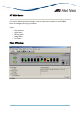
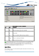
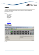
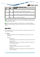
Device Manager LEDs for the AT-8948
LED State Description
PWR 1 and
PWR 2
Green
Gray
There is a power supply unit (PSU) in the PSU bay.
There is no power supply unit (PSU) in the PSU bay.
FAN Green
Gray
There is a functioning Fan Only Module (FOM) in the PSU bay.
There is no functioning Fan Only Module (FOM) in the PSU bay.
DUPLEX Green
Orange
The port is operating at full duplex.
The port is operating at half duplex.
Note - The current firmware version does not allow Device Manager to display the correct
image for SFP module 'AT-SPFXBD-LC-13'. As a result, the SFP image that will be displayed
is the generic SFP Fiber image.
Note - When a single PSU is installed, it is advised to install it in the device's PSU Bay 2 in
order for the Device Manager to display correct information on the Fan and Power Supply
modules.
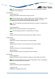
Agent Menu
From the Agent menu, you can view and edit the system information for the switch, or log
into the CLI using Telnet.
System Info
Standard
Displays basic system information, including system name, location, contact and
description.
Enterprise
CPU Utilization
Displays information about the CPU utilization over different periods of time.
Power Supply Info
Displays information about the power supply, redundant power supply and
power supply monitoring.
Fan and Power Supply
Displays information about type and status of the Fan and PSU.
Temperature
Displays information about the temperature monitored by the temperature
sensors in the device.