AlliedView™-EMS 3.10 (Full Installation) QoS MANAGER USER’S GUIDE AlliedView™-EMS 3.
TABLE OF CONTENTS 1 OVERVIEW........................................................................................................................................ 5 2 STARTING QOS MANAGER .......................................................................................................... 6 3 MAIN WINDOW .............................................................................................................................. 7 3.1 INITIAL WINDOW ...................................................
6.3.5 Ports...................................................................................................... 51 6.3.6 Scheduling ............................................................................................ 51 6.3.7 Quick Setup.......................................................................................... 52 6.3.8 Notes..................................................................................................... 52 6.4 AT-9000/24 .......................................
6.9.4 Policies ................................................................................................ 125 6.9.5 Ports.................................................................................................... 126 6.9.6 Scheduling .......................................................................................... 126 6.9.7 Quick Setup........................................................................................ 126 6.9.8 Notes...............................................
1 Overview QoS Manager is a tool that enables you to configure Quality of Service or Class of Service on a device. Topics • • • • • Starting QoS Manager Main Window Basic Operations Menus Device Support 1 Overview AlliedView™-EMS 3.
2 Starting QoS Manager QoS Manager can be started from Device Manager or from the command line. In a Windows environment, QoS Manager can be started from the AlliedViewEMS program folder or from the Run command of the Start menu. You can start QoS Manager from Device Manager by clicking on Tool > QoS Manager on the main menu or by clicking on the QoS Manager icon on the toolbar.
3 Main Window When started, QoS Manager displays one of the following windows, depending on how it is started. Topics: • • Initial Window QoS/CoS Information Window 3 Main Window AlliedView™-EMS 3.
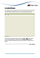
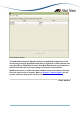
3.1 Initial Window If the target host is not specified, or if one or more connection parameters do not match what is configured on the host, the following window appears. Initial Window To specify a target host from this window, select File → Open . If the target host is a device model that is supported by QoS Manager, the QoS/CoS Information Window displaying the target host's QoS/CoS configuration will appear. 3 Main Window AlliedView™-EMS 3.
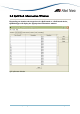
3.2 QoS/CoS Information Window Depending on whether the target host is a QoS-based or a CoS-based device, QoS Manager will display the appropriate information window. QoS Information Window AlliedView™-EMS 3.
CoS Information Window The QoS/CoS Information Window displays the QoS/CoS configuration of the device being managed. QoS/CoS information is organized via tabs with each tab corresponding to a QoS/CoS element. Each QoS/CoS element is presented in a table format with each row representing one instance of the element. QoS/CoS elements, as well as the fields available under each element, may vary from one device series to another.
4 Basic Operations This chapter discusses the basic operations within QoS Manager windows. Topics • • • • • Add Modify Delete Inline Table Editing Apply 4 Basic Operations AlliedView™-EMS 3.
4.1 Add The Add operation is only available on QoS-based devices and only for the following QoS elements: • • • • Classifiers Flow Groups Traffic Classes Policies To add a new instance of a QoS element, click on the Add button to display the Add window. The Add window is presented as a two-column table (Property Sheet). The left column represents the available fields for the QoS element, while the right column represents their corresponding values.
To configure a field, click on the value cell of that field. Depending on the field being configured, the value cell will become one of the following: • • • • Editable - a value is keyed in manually Dropdown Selection - a single value is selected from a pre-defined list of values Editable Dropdown Selection - a single value can either be selected from a pre-defined list of values or keyed in manually Multiple Selection - one or more values can be selected from a predefined list of values.
4.2 Modify The Modify operation is only available on QoS-based devices and only for the following QoS elements: • • • • Classifiers Flow Groups Traffic Classes Policies To modify the field values of an existing instance of a QoS element, select a table row from the QoS Information Window then click on the Modify button. The Modify window is the same as the Add window except that the value cells will now contain the values which were previously set.
After modifying or setting all the desired fields, you can complete the Modify operation by clicking the OK button. If you wish to cancel the operation without applying the changes, click on the Cancel button. 4 Basic Operations AlliedView™-EMS 3.
4.3 Delete The Delete operation is only available on QoS-based devices and only for the following QoS elements: • • • • Classifiers Flow Groups Traffic Classes Policies To delete an instance of a QoS element, select a table row from the QoS Information Window then click on the Delete button. As a safety measure, before the selected element is deleted, you will be asked to confirm the action. 4 Basic Operations AlliedView™-EMS 3.
4.4 Inline Table Editing Inline table editing is available for both QoS-based and CoS-based devices. It makes it relatively easy to manipulate table data directly on-screen without having to use a Submit button or to go into some kind of 'edit' mode. For QoSbased devices, inline table editing is used to configure table fields in the Add and Modify operations as well as in the Ports and Scheduling tabs. For CoS-based devices, inline table editing is used to configure table fields in all tabs.
4.5 Apply QoS/Cos configuration changes made through Add/Modify/Delete operations or Inline Table Editing will not be immediately reflected on the device. QoS Manager just stores these changes locally until an Apply operation is performed. To apply QoS/CoS configuration changes to the device, click on the Apply button. As a safety measure, before the operation is performed, you will be asked to confirm the action.
When the operation is completed, a Results/Summary window will be displayed. This window will indicate whether the operation was successful or not. Also, this window will display a log of the commands that were issued to the device in the course of the operation. If the operation was successful, the Save Configuration button will be enabled to allow you to save the applied changes to the configuration file of the device. To close the Results/Summary window, click on the OK button.
5 Menus This chapter describes the items on QoS Manager's main menu. Topics: • • • File Tools Help 5 Menus AlliedView™-EMS 3.
5.1 File The File menu lets you connect to and disconnect from a target host, check the properties of the target host, or exit QoS Manager. Topics: • • • Open Close Exit 5.1.1 Open This option allows you to specify a target host to connect to. When you select File > Open, the following dialog box appears. To connect to the device, fill in parameters in the dialog box, and click OK. Note - This option is not available if QoS Manager is already connected to a target host.
SNMP Version This drop down list allows you to select the SNMP version to use in managing the target device. Note - Before choosing "v2c" or "v3", make sure that the target device you are connecting to supports SNMP v2c and/or SNMP v3 respectively. Settings If the Version is set to "v1" or "v2c", this button opens the SNMP v1/v2c Settings window. Otherwise, if the Version is set to "v3", this button opens the SNMP v3 Settings window.
SNMP v3 Settings dialog box User Account Name This is the SNMPv3 User Account to be used for accessing the MIB of the target device. Make sure to specify a User Account that has already been configured on the target device. Security Level This is the Security Level for the User Account Name that you have specified. Make sure to set the Security Level that is configured for the User Account Name on the target device.
SHA Use HMAC-SHA-96 protocol Authentication Password If the Security Level is "Auth / No Priv" or "Auth / Priv", you need to specify an Authentication Password that is configured for the User Account Name on the target device. Privacy Protocol If the Security Level is "Auth / Priv", you need to specify a Privacy Protocol.
5.1.3 Exit This option terminates connection to the target host and closes the QoS Manager application. 5 Menus AlliedView™-EMS 3.
5.2 Tools The Tools menu lets you refresh the contents of the QoS/CoS Information Window and restart the currently connected device. It also provides a quick method for configuring QoS specifically for voice and video. Topics: • • • Quick Setup Refresh Reboot 5.2.1 Quick Setup Quick Setup provides a two-step process for creating a simple QoS configuration for voice and/or video on the target device.
You will now be presented with default settings that you may adjust or fine-tune depending on the requirements of your network. After you complete the adjustments, click OK to complete the setup. AlliedView™-EMS 3.
A Summary window will be displayed. The Summary window will contain a list of QoS elements and settings that will be created by the Quick Setup function. After confirming the message, you will be returned to the QoS Information Window where you can do further revisions to or fine-tuning on the newly created QoS elements. Note that the Quick Setup function is only available for QoS-based devices. 5.2.
5.2.3 Reboot This option displays a reboot confirmation dialog box. Note - This option is only available if QoS Manager is already connected to a target host. Upon confirmation, the device will be rebooted. While the Reboot is in progress, a progress window will be displayed. Once completed, the progress window will close and the contents of the QoS/CoS Information Window should now be updated with the latest settings from the device. 5 Menus AlliedView™-EMS 3.
5.3 Help The Help menu lets you view the online user's guide as well as some basic information about the application. Topics: • • Index About 5.3.1 Index This option displays the main page of the online user's manual. 5.3.2 About This option displays version and copyright information for QoS Manager. It also displays a list of the currently supported devices. 5 Menus AlliedView™-EMS 3.
6 Device Support This section describes, on a per device series basis, the specific QoS/CoS attributes displayed in the QoS/CoS Information Window, the configurable fields available in the Add, Modify and Quick Setup windows, and any known issues and/or operational notes. Topics: • • • • • • • • • AT-8000S Series AT-8600 Series AT-8800 Series AT-9000/24 AT-9400 Series AT-9900 Series AT-x900-24x Series Rapier 24i SwitchBlade Series 6 Device Support AlliedView™-EMS 3.
6.1 AT-8000S Series Topics: • • • • • • General Port Scheduling CoS Priority DSCP Priority Bandwidth 6.1.1 General Setting QoS Mode Description Enables/Disables quality of service (QoS) on the device Trust Mode Configures the system to the basic mode and trust state. It is used to specify whether the ports are trusted and which field of the ingress packets to use to classify traffic. Value • • enabled disabled • CoS - ingress packets are classified using packet CoS values.
Default CoS Specifies the default CoS value Range: 0-7 of an interface 6.1.3 Scheduling Setting Scheduling Description Value Configures the number of • Strict Priority - higher expedite queues. It is used to priority queues are specify the scheduling method emptied before any to use. packets are transmitted from lower priority queues • Weighted Priority packets are transmitted from all queues in a round-robin fashion based on the queue weights 6.1.
Column Name Description Ingress Status Rate Limit Egress Status CIR CBS Value • channels - ch1, ch2..chn where: • n = port/channel number • s = stack id Enables/Disables the Rate Limit • enabled field • disabled Specifies the maximum kilobits Range: 62-1000000 per second of ingress traffic on a port Note - This field does not apply to channels.
6.2 AT-8600 Series Topics: • • • • • • • • Classifiers Flow Groups Traffic Classes Policies Ports Scheduling Quick Setup Notes 6.2.1 Classifiers 6.2.1.1 QoS Information Window Column Name Classifier ID Description Lists the Rule ID of packet-matching rules available 6.2.1.
Property Name Ethernet Format Description Valid Values Specifies the Ethernet encapsulation type of the packet. This can be set by selecting any of the following values: • • • • • • • • • • • Source IP Address Specifies the source IP Address This can be set by entering an (either host or host/subnet) of IP Address in dotted decimal an IP packet. notation with an optional mask • • Destination IP Specifies the destination IP Address Address (either host or host/subnet) of an IP packet.
Property Name Description Valid Values • • • • IP Type of Service Destination IPX Address IPX Packet This can also be set by entering an integer from 0-255. Range: any, 0-7 Specifies the value of the precedence field within the TOS (Type of Service) byte of an IP packet. Specifies the destination This can be set by entering a 4network address of an IPX byte hexadecimal value. packet. (00000001-FFFFFFFF) This can also be set to "any".
Property Name Description Valid Values following: • • • • • • • • Source MAC Address Specifies the source MAC address of the packet. NCP SAP RIP NNB DIAG NLSP IPXWAN any This can be set by entering a MAC address string using the following format: • XX-XX-XX-XX-XX-XX This can also be set to "any". Destination This parameter specifies the This can be set by entering a MAC Address destination MAC address of the MAC address string using the packet.
Property Name Match3 Mask3 Offset3 Protocol Source TCP Port Destination TCP Port TCP Flags Description is to be checked. Specifies the actual data to match Specifies whether the corresponding bit in the Match3 parameter is "on" for a match or "don't care" for a match. Specifies the location or offset where the pattern for Match3 is to be checked. Specifies the protocol of the packet. Valid Values This can be set by entering a 2byte hex number. (0000-FFFF) This can be set by entering a 2byte hex number.
6.2.2 Flow Groups 6.2.2.1 QoS Information Window Column Name Flow Group ID Description Classifiers Description Lists the ID of Flow Groups available A brief description of the Flow Group. List of Classifiers associated with this Flow Group 6.2.2.2 Add/Modify Flow Group Property Name Description Flow Group ID Specifies the unique identifier for the flow group. (cannot be modified) Description Specifies a brief description of the Flow Group.
6.2.3.2 Add/Modify Traffic Class Property Name Description Traffic Class ID Specifies the unique identifier for this Traffic Class. (cannot be modified) Description Specifies a brief description of the Traffic Class. Exceed Action Specifies the action to take if the traffic classes maxbandwidth is exceeded. Exceed Remark Specifies the DSCP Value replacement value for traffic that exceeds the maxbandwidth. Mark Value Specifies a replacement value to write into the DSCP (TOS) field for all packets.
6.2.4 Policies 6.2.4.1 QoS Information Window Column Name Policy ID Description Traffic Classes Description Lists the ID of Policies available A brief description of the Policy List of Traffic Classes associated with this Policy 6.2.4.2 Add/Modify Policy Property Name Description Specifies the unique identifier Policy ID for the Policy. (cannot be modified) Description Specifies a brief description of the Policy.
Max Latency passed to the next queue. Maximum permissible elapsed time between packets Range: 0, 16-4080 transmitted from this queue. 6.2.7 Quick Setup Property Name Description Valid Values Source UDP Specifies the UDP source port Range: 0-65535 Port of an UDP/IP packet. Default for VOICE: 1719 Default for VIDEO: 1024 Priority Specifies the priority that will Range: none, 0-7 be assigned for this setup.
6.3 AT-8800 Series Topics: • • • • • • • • Classifiers Flow Groups Traffic Classes Policies Ports Scheduling Quick Setup Notes 6.3.1 Classifier 6.3.1.1 QoS Information Window Column Name Classifier ID Description Lists the Rule ID of packet-matching rules available 6.3.1.
Property Name Ethernet Format Description Valid Values Specifies the Ethernet encapsulation type of the packet. This can be set by selecting any of the following values: • • • • • • • • • • • Source IP Address Specifies the source IP Address This can be set by entering an (either host or host/subnet) of IP Address in dotted decimal an IP packet. notation with an optional mask • • Destination IP Specifies the destination IP Address Address (either host or host/subnet) of an IP packet.
Property Name Description Valid Values • • • • IP Type of Service Destination IPX Address IPX Packet This can also be set by entering an integer from 0-255. Range: any, 0-7 Specifies the value of the precedence field within the TOS (Type of Service) byte of an IP packet. Specifies the destination This can be set by entering a 4network address of an IPX byte hexadecimal value. packet. (00000001-FFFFFFFF) This can also be set to "any".
Property Name Description Valid Values following: • • • • • • • • Source MAC Address Specifies the source MAC address of the packet. NCP SAP RIP NNB DIAG NLSP IPXWAN any This can be set by entering a MAC address string using the following format: • XX-XX-XX-XX-XX-XX This can also be set to "any". Destination This parameter specifies the This can be set by entering a MAC Address destination MAC address of the MAC address string using the packet.
Property Name Match3 Mask3 Offset3 Protocol Description is to be checked. Specifies the actual data to match Specifies whether the corresponding bit in the Match3 parameter is "on" for a match or "don't care" for a match. Specifies the location or offset where the pattern for Match3 is to be checked. Specifies the protocol of the packet. Valid Values This can be set by entering a 2byte hex number. (0000-FFFF) This can be set by entering a 2byte hex number.
6.3.2 Flow Groups 6.3.2.1 QoS Information Window Column Name Flow Group ID Description Classifiers Description Lists the ID of Flow Groups available A brief description of the Flow Group. List of Classifiers associated with this Flow Group 6.3.2.2 Add/Modify Flow Group Property Name Description Flow Group ID Specifies the unique identifier for the flow group. (cannot be modified) Description Specifies a brief description of the Flow Group.
6.3.3.2 Add/Modify Traffic Class Property Name Description Traffic Class ID Specifies the unique identifier for this Traffic Class. (cannot be modified) Description Specifies a brief description of the Traffic Class. Exceed Action Specifies the action to take if the traffic classes maxbandwidth is exceeded. Exceed Remark Specifies the DSCP Value replacement value for traffic that exceeds the maxbandwidth. Mark Value Specifies a replacement value to write into the DSCP (TOS) field for all packets.
6.3.4 Policies 6.3.4.1 QoS Information Window Column Name Policy ID Description Traffic Classes Description Lists the ID of Policies available A brief description of the Policy List of Traffic Classes associated with this Policy 6.3.4.2 Add/Modify Policy Property Name Description Specifies the unique identifier Policy ID for the Policy. (cannot be modified) Description Specifies a brief description of the Policy.
Max Latency passed to the next queue. Maximum permissible elapsed time between packets Range: 0, 16-4080 transmitted from this queue. 6.3.7 Quick Setup Property Name Description Valid Values Source UDP Specifies the UDP source port Range: 0-65535 or a port range Port of an UDP/IP packet. (n-m). Default for VOICE: 1719 Default for VIDEO: 1024 Priority Specifies the priority that will Range: none, 0-7 be assigned for this setup.
6.4 AT-9000/24 Topics: • • • General Traffic Class Port Priority 6.4.1 General Setting QoS Status Description Enables/Disables quality of service (QoS) on the device Value • • enabled disabled 6.4.2 Traffic Class Column Name Description Value Lists the CoS values available Range: 0-7 Traffic Class (cannot be modified) Queue Specifies the queue number to Range: 0-3 which the CoS value is mapped 6.4.
6.5 AT-9400 Series Topics: • • • • • • • • Classifiers Flow Groups Traffic Classes Policies Ports Scheduling Quick Setup Notes 6.5.1 Classifiers 6.5.1.1 QoS Information Window Column Name Classifier ID Description Lists the Rule ID of packet-matching rules available 6.5.1.
Property Name Description Valid Values Ethernet Format Specifies the Ethernet encapsulation type of the packet. This can also be set to "any". • EthII-Untagged • EthII-Tagged • 802.2-Untagged • 802.2-Tagged Priority Specifies the priority level of a Range: 0-7 tagged Ethernet frame. Specifies the VID number and This can be set by selecting name of a tagged or port-based from a list of available VLANs VLAN.
Property Name Description Valid Values Destination IP Specifies the destination IP Address Address (either host or host/subnet) of an IP packet. Where M = 0-32. This can be set by entering an IP Address in dotted decimal notation with an optional mask • • Source TCP Port Destination TCP Port Source UDP Port Destination UDP Port TCP Flags NNN.NNN.NNN.NNN NNN.NNN.NNN.NNN/M Where M = 0-32. Specifies the TCP source port Range: 0-65535 of a TCP/IP packet.
Property Name Description Description Specifies a brief description of the Flow Group. Mark Value Valid Values To set this value, enter an alphanumeric string from 1-15 characters. Range: any, 0-63 Specifies a replacement value to write into the DSCP (TOS) field for all packets. Range: none, 0-7 Priority Specifies the priority that traffic belonging to this Flow Group has.
6.5.3.1 Add/Modify Traffic Class Property Name Description Traffic Class ID Specifies the unique identifier for this Traffic Class. (cannot be modified) Description Specifies a brief description of the Traffic Class. Valid Values Range: 0-511 To set this value, enter an alphanumeric string from 1-15 characters. • drop • remark Exceed Action Specifies the action to take if the traffic classes maxbandwidth is exceeded.
Property Name Description Valid Values to TOS value in the ToS priority field • no will be replaced with the value in the 802.1p priority field on IPv4 packets. Select from a list of available Flow Group Specifies a list of the Flow Flow Group IDs. List Groups currently assigned to this Traffic Class. 6.5.4 Policies 6.5.4.
Property Name Description a destination mirror port. Valid Values • no Ingress Port Select from a list of available Port IDs. Egress Port Traffic Class List Specifies a list of the Ingress Ports currently assigned to this Policy. Specifies a list of the Egress Ports currently assigned to this Policy. Specifies a list of the Traffic Classes currently assigned to this Policy. Select from a list of available Port IDs. Select from a list of available Traffic Class IDs. 6.5.5 Ports 6.5.5.
6.5.7 Quick Setup Property Name Description Valid Values Source UDP Specifies the UDP source port Range: 0-65535 Port of a UDP/IP packet. Default for VOICE: 1719 Default for VIDEO: 1024 Priority Specifies the priority that will Range: none, 0-7 be assigned for this setup. Default for VOICE: 7 Default for VIDEO: 4 Maximum Specifies the maximum • 0-16000000 kbps Bandwidth bandwidth available to this • 0-16000 Mbps (decimal setup.
6.6 AT-9900 Series Topics: • • • • • • • • Classifiers Flow Groups Traffic Classes Policies Ports Scheduling Quick Setup Notes 6.6.1 Classifiers 6.6.1.1 QoS Information Window Column Name Classifier ID Description Lists the Rule ID of packet-matching rules available 6.6.1.2 Add/Modify Classifier Property Name Description Rule ID Uniquely identifies the packet(cannot be matching rule modified) Source MAC Specifies the source MAC Address address of the packet.
Property Name Description Valid Values mask, the value of the bit at the • XX-XX-XX-XX-XX-XX same position in the byte value of the MAC address is used to determine a match. If a bit in This can also be set to "any". the Source MAC Address parameter is 0, the corresponding bit in the Source MAC Address parameters is ignored. Specifies the masks to be used This can be set by entering a Destination MAC address string using the MAC Address on the Destination MAC Address.
Property Name Description destination VLAN. Valid Values Inner Tag Protocol ID Specifies the TPID in the second 802.1Q tag in the packet. Inner VLAN Priority Inner VLAN This can be set by entering a 4byte hex number from 0000FFFF. This can also be set to "any". Range: any, 0-7 Specifies the second 802.1P field in the packet. Specifies the tunnelled VLAN This can be set by selecting ID in the second 802.1Q tag in from a list of available VLANs or "any". the packet. This parameter specifies the • 802.
Property Name Description IP DSCP IP Type of Service IP Protocol Valid Values • DEC MOP REM CONS • DEC DECNET • DEC LAT • DEC DIAGNOSTIC • DEC CUSTOMER • DEC LAVC • RARP • DEC LANBRIDGE • DEC ENCRYPTION • APPLETALK • IBM SNA • IPX ETHII • APPLETALK AARP • SNMP • IPV6 ETHII • IPX 802.3 • ETHERTALK 2 • ETHERTALK 2 AARP • IPX SNAP • any This can also be set by entering a 1- to 5-byte hexadecimal value (00-FFFFFFFFFF).
Property Name Description Source IP Address Valid Values • any This can also be set by entering an integer from 0-255. Specifies the source IP address This can be set by entering an (either host or subnet) of an IP IPV4 or IPV6 address using the packet. following format: • • IPv4 address[/mask] IPv4 is in dotted decimal notation, mask is 0..32. IPv6 address[/mask] IPv6 is in colon separated hex digit notation, mask is 0..128. This value can also be set to "any".
Property Name Description Valid Values • DIAG • NLSP • IPXWAN • any Destination IPX Socket This can be set by entering a 4byte hexadecimal value (0000FFFF) or by selecting one of the following: • NCP • SAP • RIP • NNB • DIAG • NLSP • IPXWAN • any Specifies the destination IPX socket number of an IPX packet. Source TCP Port Destination TCP Port Source UDP Port Destination UDP Port Source L4 Mask Specifies the TCP source port of a TCP/IP packet. Specifies the TCP destination port of a TCP/IP packet.
Property Name Description Valid Values decimal number in the range 0 to 37. This specifies the location of the byte to match. It refers to the offset from the start of Layer 5, after the UDP or TCP header. • bytevalue, which is a 2digit hexadecimal number. This specifies the value of the byte at the position in the frame that is determined by byteoffset. The classifier matches packets that have this value at this location. • (optionally) bytemask, which is a 2-digit hexadecimal number.
Property Name Description IPv4 packet. Valid Values one of the following values: • • • • • • • • • • • • • • • • • • ICMP Code Specifies the ICMP code of an IPv4 packet. This can also be set by entering a value from 0-255. This can be set by selecting any one of the following values: • • • • • • • • • • • • • • • • • • • • AlliedView™-EMS 3.
Property Name Description IGMP Type EIPByte01-16 Specifies the IGMP type of an IPv4 packet. Valid Values • PRECEDENT • PROTUNREACH • PTRPROBLEM • SOURCEROUTE • TTL This can also be set by entering a value from 0-255. This can be set by selecting any one of the following values: • QUERY • V1REPORT • DVMRP • PIMV1 • CTRACE • V2REPORT • V2LEAVE • MCTRACERESPONSE • MCTRACE • V3REPORT • MRADVERT • MRSOLICIT • MRTERMINATION • any This can also be set by entering a 2-byte hexadecimal number 00-FF.
Property Name Description • • • Valid Values byteoffset is a decimal number in the range 0 to 65. This specifies the location of the byte to match. It refers to the offset from the start of Layer 3, after the Layer 2 encapsulation format of an Ethernet frame. bytevalue is a 2-digit hexadecimal number. This specifies the value of the byte at the frame position determined by the byteoffset. The classifier matches packets that have this value at this location.
6.6.2.2 Add/Modify Flow Group Property Description Name Specifies the unique Flow Group ID identifier for the Flow (cannot be Group. modified) Description Specifies a brief description of the Flow Group. Mark Value This parameter specifies a replacement value to write into the DSCP (TOS) field for all packets. Action Specifies the action to be performed on traffic belonging to the Flow Group. Port Valid Values Range: 0-1023 To set this value, enter an alphanumeric string from 1-15 characters.
Property Name Classifier List Description Valid Values specified by the port parameter, so the VLAN must contain this port. Specifies a list of the Classifiers currently assigned to this Flow Group. Select from a list of available classifier IDs. 6.6.3 Traffic Classes 6.6.3.
Property Name Class Description Valid Values acknowledges any • YES previous bandwidth class assigned to flows processed by the default traffic class. Mark Value Specifies an explicit value • 0-63 to use as an index into the • none DSCPMAP table when the premarking parameter is usemarkvalue. This can be set by entering a value using Maximum Specifies the maximum Bandwidth bandwidth available to the one the following formats: traffic class.
Property Name Size Description Valid Values tolerance for the Minumum Bandwidth, or for the Maximum Bandwidth when the Minimum Bandwidth is none. one the following formats: • • • • 0-16777216 bytes 0~16384 KB (decimal point supported) 0~16 MB (decimal point supported) 0~0.
Property Name Description Valid Values detected. VLAN Specifies the VLAN where unclassified traffic is sent when action is sendvlanport. Traffic is sent over the port specified by the port parameter so the VLAN must contain that port. Port Specifies the port where unclassified traffic is sent when action is sendvlanport. The port must belong to the VLAN specified by the vlan parameter. Flow Specifies a list of the Flow Group List Groups currently assigned to this Traffic Class.
Property Name Description Valid Values • • • SENDMIRROR SENDMIRROR,SENDVLANPORT SENDVLANPORT Determines whether or • yes not to drop frames • no exceeding the default traffic class maximum bandwidth setting. Determines whether or • yes not the metering stage • no acknowledges any previous bandwidth class assigned to flows processed by the default traffic class.
Property Name Description Valid Values • • Default Traffic Class Min Burst Size supported) 0-16 Gbps (decimal point supported) none This can be set by entering a value using Specifies the burst tolerance for the default one the following formats: traffic class minumum • 0-16777216 bytes bandwidth, or for the • 0~16384 KB (decimal point default traffic class supported) maximum bandwidth • 0~16 MB (decimal point when the default traffic supported) class minimum bandwidth • 0~0.
Property Name Class Storm Action Default Traffic Class Storm Timeout Mark Value Port VLAN Traffic Class List Description detected on a port. Valid Values • VLANDISABLE Specifies the length of time the port remains disabled after a storm is detected. This value can be set by entering a number from 1-86400. This can also be set to "none". This parameter specifies an explicit value to use as an index into the DSCPMAP table when the dtcpremarking parameter is usemarkvalue.
6.6.6 Scheduling Column Name Description Port Specifies the port ID. (cannot be modified) Valid Values This can be set by selecting any one of the following values: • • port 1 - n (n = number of ports available) none This value can be set by entering a number from 016000000. Alternatively a value from 016000Mbps can be specified. 0-16Gbps can also be specified. Specifies the method by which • Strict frames on each egress queue is • WRR1 allocated bandwidth for • WRR2 transmission onto the line.
Column Name Description Valid Values bandwidth with other queues in the WRR2 group according to their relative values of wwrweight. The WRR2 group can transmit frames when both the strict and WRR1 scheduling groups are empty. The initial value is strict. WRR Weight Length Specifies the weight to use for This value can be set by the queue when it is configured entering a number from 6-255. to use one of the WRR groups.
Property Name Description Bandwidth bandwidth available to this setup. Port Assignment Valid Values • 0-16000 Mbps (decimal point supported) • 0-16 Gbps (decimal point supported) Default for VOICE: 128kbps Default for VIDEO: 256kbps Specifies a list of ports that will Select from a list of available be affected by this setup. Ports. Default for VOICE: no ports Default for VIDEO: no ports 6.6.
• To configure the Storm Status property, the switch must be in enhanced mode. • When the Storm Status property is configured, the Storm Window and Storm Rate properties should also be configured. • Values entered for the Storm Window property are automatically rounded off to the nearest hundreds. • When the TAG Protocol ID classifier property is not set to any value and the VLAN classifier property is set to 'any', the current firmware version automatically sets the TAG Protocol ID to '8100'.
6.7 AT-x900-24x Series Topics: • • • • • • • • Classifiers Flow Groups Traffic Classes Policies Ports Scheduling Quick Setup Notes 6.7.1 Classifiers 6.7.1.1 QoS Information Window Column Name Classifier ID Description Lists the Rule ID of packet-matching rules available 6.7.1.2 Add/Modify Classifier Property Name Description Rule ID Uniquely identifies the packet(cannot be matching rule modified) Source MAC Specifies the source MAC Address address of the packet.
Property Name Description Valid Values mask, the value of the bit at the • XX-XX-XX-XX-XX-XX same position in the byte value of the MAC address is used to determine a match. If a bit in This can also be set to "any". the Source MAC Address parameter is 0, the corresponding bit in the Source MAC Address parameters is ignored. Specifies the masks to be used This can be set by entering a Destination MAC address string using the MAC Address on the Destination MAC Address.
Property Name Description destination VLAN. Valid Values Inner Tag Protocol ID Specifies the TPID in the second 802.1Q tag in the packet. Inner VLAN Priority Inner VLAN This can be set by entering a 4byte hex number from 0000FFFF. This can also be set to "any". Range: any, 0-7 Specifies the second 802.1P field in the packet. Specifies the tunnelled VLAN This can be set by selecting ID in the second 802.1Q tag in from a list of available VLANs or "any". the packet. This parameter specifies the • 802.
Property Name Description IP DSCP IP Type of Service IP Protocol Valid Values • DEC MOP REM CONS • DEC DECNET • DEC LAT • DEC DIAGNOSTIC • DEC CUSTOMER • DEC LAVC • RARP • DEC LANBRIDGE • DEC ENCRYPTION • APPLETALK • IBM SNA • IPX ETHII • APPLETALK AARP • SNMP • IPV6 ETHII • IPX 802.3 • ETHERTALK 2 • ETHERTALK 2 AARP • IPX SNAP • any This can also be set by entering a 1- to 5-byte hexadecimal value (00-FFFFFFFFFF).
Property Name Description Source IP Address Valid Values • any This can also be set by entering an integer from 0-255. Specifies the source IP address This can be set by entering an (either host or subnet) of an IP IPV4 or IPV6 address using the packet. following format: • • IPv4 address[/mask] IPv4 is in dotted decimal notation, mask is 0..32. IPv6 address[/mask] IPv6 is in colon separated hex digit notation, mask is 0..128. This value can also be set to "any".
Property Name Description Valid Values • DIAG • NLSP • IPXWAN • any Destination IPX Socket This can be set by entering a 4byte hexadecimal value (0000FFFF) or by selecting one of the following: • NCP • SAP • RIP • NNB • DIAG • NLSP • IPXWAN • any Specifies the destination IPX socket number of an IPX packet. Source TCP Port Destination TCP Port Source UDP Port Destination UDP Port Source L4 Mask Specifies the TCP source port of a TCP/IP packet. Specifies the TCP destination port of a TCP/IP packet.
Property Name Description Valid Values decimal number in the range 0 to 37. This specifies the location of the byte to match. It refers to the offset from the start of Layer 5, after the UDP or TCP header. • bytevalue, which is a 2digit hexadecimal number. This specifies the value of the byte at the position in the frame that is determined by byteoffset. The classifier matches packets that have this value at this location. • (optionally) bytemask, which is a 2-digit hexadecimal number.
Property Name Description IPv4 packet. Valid Values one of the following values: • • • • • • • • • • • • • • • • • • ICMP Code Specifies the ICMP code of an IPv4 packet. This can also be set by entering a value from 0-255. This can be set by selecting any one of the following values: • • • • • • • • • • • • • • • • • • • • AlliedView™-EMS 3.
Property Name Description IGMP Type EIPByte01-16 Specifies the IGMP type of an IPv4 packet. Valid Values • PRECEDENT • PROTUNREACH • PTRPROBLEM • SOURCEROUTE • TTL This can also be set by entering a value from 0-255. This can be set by selecting any one of the following values: • QUERY • V1REPORT • DVMRP • PIMV1 • CTRACE • V2REPORT • V2LEAVE • MCTRACERESPONSE • MCTRACE • V3REPORT • MRADVERT • MRSOLICIT • MRTERMINATION • any This can also be set by entering a 2-byte hexadecimal number 00-FF.
Property Name Description • • • Valid Values byteoffset is a decimal number in the range 0 to 65. This specifies the location of the byte to match. It refers to the offset from the start of Layer 3, after the Layer 2 encapsulation format of an Ethernet frame. bytevalue is a 2-digit hexadecimal number. This specifies the value of the byte at the frame position determined by the byteoffset. The classifier matches packets that have this value at this location.
6.7.2.2 Add/Modify Flow Group Property Description Name Specifies the unique Flow Group ID identifier for the Flow (cannot be Group. modified) Description Specifies a brief description of the Flow Group. Mark Value This parameter specifies a replacement value to write into the DSCP (TOS) field for all packets. Action Specifies the action to be performed on traffic belonging to the Flow Group. Port Valid Values Range: 0-1023 To set this value, enter an alphanumeric string from 1-15 characters.
Property Name Classifier List Description Valid Values specified by the port parameter, so the VLAN must contain this port. Specifies a list of the Classifiers currently assigned to this Flow Group. Select from a list of available classifier IDs. 6.7.3 Traffic Classes 6.7.3.
Property Name Class Description Valid Values acknowledges any • YES previous bandwidth class assigned to flows processed by the default traffic class. Mark Value Specifies an explicit value • 0-63 to use as an index into the • none DSCPMAP table when the premarking parameter is usemarkvalue. This can be set by entering a value using Maximum Specifies the maximum Bandwidth bandwidth available to the one the following formats: traffic class.
Property Name Size Description Valid Values tolerance for the Minumum Bandwidth, or for the Maximum Bandwidth when the Minimum Bandwidth is none. one the following formats: • • • • 0-16777216 bytes 0~16384 KB (decimal point supported) 0~16 MB (decimal point supported) 0~0.
Property Name Description Valid Values detected. VLAN Specifies the VLAN where unclassified traffic is sent when action is sendvlanport. Traffic is sent over the port specified by the port parameter so the VLAN must contain that port. Port Specifies the port where unclassified traffic is sent when action is sendvlanport. The port must belong to the VLAN specified by the vlan parameter. Flow Specifies a list of the Flow Group List Groups currently assigned to this Traffic Class.
Property Name Description Valid Values • • • SENDMIRROR SENDMIRROR,SENDVLANPORT SENDVLANPORT Determines whether or • yes not to drop frames • no exceeding the default traffic class maximum bandwidth setting. Determines whether or • yes not the metering stage • no acknowledges any previous bandwidth class assigned to flows processed by the default traffic class.
Property Name Description Valid Values • • Default Traffic Class Min Burst Size supported) 0-16 Gbps (decimal point supported) none This can be set by entering a value using Specifies the burst tolerance for the default one the following formats: traffic class minumum • 0-16777216 bytes bandwidth, or for the • 0~16384 KB (decimal point default traffic class supported) maximum bandwidth • 0~16 MB (decimal point when the default traffic supported) class minimum bandwidth • 0~0.
Property Name Class Storm Action Default Traffic Class Storm Timeout Mark Value Port VLAN Traffic Class List Description detected on a port. Valid Values • VLANDISABLE Specifies the length of time the port remains disabled after a storm is detected. This value can be set by entering a number from 1-86400. This can also be set to "none". This parameter specifies an explicit value to use as an index into the DSCPMAP table when the dtcpremarking parameter is usemarkvalue.
6.7.6 Scheduling Column Name Description Port Specifies the port ID. (cannot be modified) Valid Values This can be set by selecting any one of the following values: • • port 1 - n (n = number of ports available) none This value can be set by entering a number from 016000000. Alternatively a value from 016000Mbps can be specified. 0-16Gbps can also be specified. Specifies the method by which • Strict frames on each egress queue is • WRR1 allocated bandwidth for • WRR2 transmission onto the line.
Column Name Description Valid Values bandwidth with other queues in the WRR2 group according to their relative values of wwrweight. The WRR2 group can transmit frames when both the strict and WRR1 scheduling groups are empty. The initial value is strict. WRR Weight Length Specifies the weight to use for This value can be set by the queue when it is configured entering a number from 6-255. to use one of the WRR groups.
Property Name Description Bandwidth bandwidth available to this setup. Port Assignment Valid Values • 0-16000 Mbps (decimal point supported) • 0-16 Gbps (decimal point supported) Default for VOICE: 128kbps Default for VIDEO: 256kbps Specifies a list of ports that will Select from a list of available be affected by this setup. Ports. Default for VOICE: no ports Default for VIDEO: no ports 6.7.
• When the Protocol property is configured, the Ethernet Format property should also be configured. • To configure the Storm Status property, the switch must be in enhanced mode. • When the Storm Status property is configured, the Storm Window and Storm Rate properties should also be configured. • Values entered for the Storm Window property are automatically rounded off to the nearest hundreds.
• The actual value of bytevalue that is configured for the EIPByte01-16 classifier properties is computed by performing a bitwise AND operation between the bytevalue and bytemask values supplied. Ex. bytevalue = 25 (00100101) bytemask = 3B (00111011) AND = 21 (00100001) The hexadecimal value 21 will be the actual value configured. 8 Device Support AlliedView™-EMS 3.
6.8 Rapier 24i Topics: • • • • • • • • Classifiers Flow Groups Traffic Classes Policies Ports Scheduling Quick Setup Notes 6.8.1 Classifiers 6.8.1.1 QoS Information Window Column Name Classifier ID Description Lists the Rule ID of packet-matching rules available 6.8.1.2 Add/Modify Classifier Property Name Description Rule ID Uniquely identifies the packet(cannot be matching rule modified) Egress Port Specifies the egress port on the switch to match for each frame.
Property Name Description Ingress Specifies the interface through Interface which the frame arrives at the switch. Valid Values This can be set by selecting the name of a pre-defined interface on the device. This can also be set to "none". Source VLAN Specifies the VLAN associated This can be set by selecting with the frame when it arrives from a list of available VLANs or "any". at the switch. Only valid in classifiers for software QoS on egress interfaces.
Property Name Description MAC Type Protocol Valid Values This value can also be set to "any". Specifies the type of destination • L2UCAST MAC address on the frame. • L2BMCAST • any Specifies the protocol of the packet This can be set by selecting any of the following values: • • • • • • Frame Relay Data Link Connection ID PPP Index PPP Protocol ID Source IP Address IP IPv6 ARP IPX NONIPIPX any This can also be set by entering a 1- to 5- byte hexadecimal value (00-FFFFFFFFFF).
Property Name Description Destination IP Specifies the destination IP Address Address (either host or host/subnet) of an IP packet Valid Values is 0..128. This value can also be set to "any". This can be set by entering an IPV4 or IPV6 address using the following format: • • IPv4 address[/mask] IPv4 is in dotted decimal notation, mask is 0..32. IPv6 address[/mask] IPv6 is in colon separated hex digit notation, mask is 0..128. This value can also be set to "any".
Property Name Description IPX Packet Specifies the value of the Packet Type field of an IPX packet. Valid Values This can be set by selecting any of the following values: • • • • • • • IP Protocol This can also be set by entering a 4-byte hexadecimal value (00FF).
Property Name Description Source TCP Specifies the TCP source port Port of a TCP/IP packet. Destination Specifies the TCP destination TCP Port port of a TCP/IP packet. Source UDP Specifies the UDP source port Port of a TCP/IP packet. Destination Specifies the UDP destination UDP Port port of a TCP/IP packet. Source IPX Specifies the source IPX socket Socket number of an IPX packet Valid Values Range: any, 0-65535 or a port range (n-m). Range: any, 0-65535 or a port range (n-m).
Property Name Description Valid Values to be checked. Match2 Specifies the actual data to This can be set by entering a 4match byte hex number. (0000-FFFF) This can be set by entering a 4Mask2 Specifies whether the byte hex number. (0000-FFFF) corresponding bit in the Match2 parameter is "on" for a match or "don't care" for a match. Offset2 Specifies the location or offset Range: 0-62 where the pattern for Match2 is to be checked.
Property Name Description Valid Values Range: none, 0-7 Priority This parameter specifies the priority that traffic belonging to this Flow Group has. Remark Specifies whether the value of • yes Priority the priority parameter is used • no to set the egress queue selection for a frame and also to replace the 802.1p priority value in the frame, or just to select the egress queue for the frame.
Property Name Description Bandwidth bandwidth available to the traffic class. Valid Values value using one the following formats: • • • Priority Remark Priority Flow Group List 0-16000000 kbps 0-16000 Mbps (decimal point supported) 0-16 Gbps (decimal point supported) Range: none, 0-7 Specifies the priority value in the IEEE Standard 802.1p tag control field that traffic belonging to this traffic class is assigned.
6.8.4 Policies 6.8.4.1 QoS Information Window Column Name Policy ID Description Traffic Classes Description Lists the ID of Policies available A brief description of the Policy List of Traffic Classes associated with this Policy 6.8.4.2 Add/Modify Policy Property Name Description Specifies the unique identifier Policy ID for the Policy. (cannot be modified) Description Specifies a brief description of the Policy.
Column Name Description Valid Values Maximum number of packets able to be transmitted from Range: 0-255 Max Packets this queue before the control is passed to the next queue. Maximum permissible elapsed Max Latency time between packets Range: 0, 16-4080 transmitted from this queue. 6.8.7 Quick Setup Property Name Description Valid Values Source UDP Specifies the UDP source port Range: 0-65535 or a port range Port of an UDP/IP packet. (n-m).
in an error message appearing when an attempt is made to modify that classifier through QoS Manager. 8 Device Support AlliedView™-EMS 3.
6.9 SwitchBlade Series Topics: • • • • • • • • Classifiers Flow Groups Traffic Classes Policies Ports Scheduling Quick Setup Notes 6.9.1 Classifiers 6.9.1.1 QoS Information Window Column Name Classifier ID Description Lists the Rule ID of packet-matching rules available 6.9.1.
Property Name Description Valid Values • • NNN.NNN.NNN.NNN NNN.NNN.NNN.NNN/M Where M = 0-32. Destination IP Specifies the destination IP This can be set by entering an Address address (either host or subnet) IP Address in dotted decimal of an IP packet. notation with an optional mask • • IP DSCP IP Protocol Where M = 0-32. Specifies the Code Point bits of This can be set by entering one the DiffServ field of an IP or more integers from 0-63. packet.
Property Name Description Valid Values • • • • • • • • Destination IPX Socket Specifies the destination IPX socket number of an IPX packet. This can also be set by entering a 2-byte hexadecimal value (0000-FFFF). This can be set by selecting any of the following values: • • • • • • • • MAC Type Protocol NCP SAP RIP NNB DIAG NLSP IPXWAN any NCP SAP RIP NNB DIAG NLSP IPXWAN any This can also be set by entering a 2-byte hexadecimal value (0000-FFFF).
Property Name Description Valid Values • • • • • • • • • • • • • • • • • • • • • • • • • • • • • • • • Source TCP Port Destination TCP Port Source UDP Port ISO CLNS IS IP ETHII X.75 INTERNET NBS INTERNET ECMA INTERNET CHAOSNET X.25 LEVEL 3 ARP XNS COMPAT BANYAN SYSTEMS BBN SIMNET DEC MOP DUMP/LD DEC MOP REM CONS DEC DECNET DEC LAT DEC DIAGNOSTIC DEC CUSTOMER DEC LAVC RARP DEC LANBRIDGE DEC ENCRYPTION APPLETALK IBM SNA IPX ETHII APPLETALK AARP SNMP IPV6 ETHII IPX 802.
Property Name Destination UDP Port Description Valid Values Specifies the UDP destination port of an UDP/IP packet. Range: any, 0-65535 6.9.2 Flow Groups 6.9.2.1 QoS Information Window Column Name Flow Group ID Description Classifiers Description Lists the ID of Flow Groups available A brief description of the Flow Group. List of Classifiers associated with this Flow Group 6.9.2.2 Add/Modify Flow Group Property Name Description Flow Group ID Specifies the unique identifier for the flow group.
Column Name Flow Groups Description List of the Flow Groups associated with this Traffic Class 6.9.3.2 Add/Modify Traffic Class Property Name Description Traffic Class ID Specifies the unique identifier (cannot be for this Traffic Class. modified) Description Specifies a brief description of the Traffic Class. Fair Hash Limit Specifies the limit used to classify hashed flow groups as "fair" or "aggressive", relative to the most "aggressive" hashed flow group.
Property Name Description Priority RED ID Statistics Counter Weight Flow Group List Valid Values • 128 • 256 • 512 • none Range: none, 0-7 This parameter specifies the priority that traffic belonging to this traffic class has. Range: none, 0-47 Specifies the Random Early Detection Curve to be used by the Random Early Detection algorithm when dropping packets to avoid congestion.
Property Name Description Description Specifies a brief description of the Policy. DTC Percent Traffic Class List Valid Values To set this value, enter an alphanumeric string from 1-15 characters. Range: 0-100 Specifies the percentage of port bandwidth allocated to the default traffic class for the policy. Select from a list of available Specifies a list of the Traffic Traffic Class IDs. Classes currently assigned to this Policy. 6.9.
Property Name Description Minimum Bandwidth Specifies the minimum bandwidth available to this setup. Valid Values supported) Default for VOICE: 128kbps Default for VIDEO: 256kbps This can be set by entering a value using one the following formats: • • • Weight Port Assignment Specifies the weight given to this traffic when distributing the bandwidth available on a QoS policy amongst all traffic classes within this setup.
© 1998-2008 Allied Telesis K. K. All rights reserved. No part of this publication may be reproduced without prior written permission from Allied Telesis, K. K. Microsoft is a registered trademark of Microsoft Corporation. Netscape Navigator is a registered trademark of Netscape Communications Corporation. All other product names, company names, logos or other designations mentioned herein are trademarks or registered trademarks of their respective owners. Allied Telesis K. K.