
Datasheet
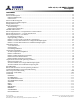
Table Of Contents
- DDR3L SDRAM
- Description
- State Diagram
- Functional Description
- Functional Block Diagrams
- Ball Assignments and Descriptions
- Package Dimensions
- Electrical Specifications
- Thermal Characteristics
- Electrical Specifications – I DD Specifications and Conditions
- Electrical Characteristics – 1.35V IDD Specifications
- Electrical Specifications – DC and AC
- ODT Characteristics
- Output Driver Impedance
- Output Characteristics and Operating Conditions
- Speed Bin Tables
- Electrical Characteristics and AC Operating Conditions
- Electrical Characteristics and AC Operating Conditions
- Command and Address Setup, Hold, and Derating
- Data Setup, Hold, and Derating
- Commands – Truth Tables
- Commands
- Input Clock Frequency Change
- Write Leveling
- Initialization
- Voltage Initialization / Change
- Mode Registers
- Mode Register 0 (MR0)
- Mode Register 1 (MR1)
- Mode Register 2 (MR2)
- Mode Register 3 (MR3)
- MODE REGISTER SET (MRS) Command
- ZQ CALIBRATION Operation
- ACTIVATE Operation
- READ Operation
- WRITE Operation
- PRECHARGE Operation
- SELF REFRESH Operation
- Extended Temperature Usage
- Power-Down Mode
- RESET Operation
- On-Die Termination (ODT)
- Dynamic ODT
- Synchronous ODT Mode
- Asynchronous ODT Mode
- Asynchronous to Synchronous ODT Mode Transition (Power-Down Exit)

List of Figures
Figure 1: DDR3L Part Numbers ........................................................................................................................ 2
Figure 2: Simplified State Diagram ................................................................................................................. 11
Figure 3: 2 Gig x 4 Functional Block Diagram .................................................................................................. 14
Figure 4: 1 Gig x 8 Functional Block Diagram .................................................................................................. 15
Figure 5: 512 Meg x 16 Functional Block Diagram ........................................................................................... 15
Figure 6: 78-Ball FBGA – x4, x8 (Top View) ...................................................................................................... 16
Figure 7: 96-Ball FBGA – x16 (Top View) ......................................................................................................... 17
Figure 8: 78-Ball FBGA – x4, x8 (SN) ................................................................................................................ 22
Figure 9: 96-Ball FBGA – x16 (HA) .................................................................................................................. 23
Figure 10: Thermal Measurement Point ......................................................................................................... 26
Figure 11: DDR3L 1.35V Input Signal .............................................................................................................. 43
Figure 12: Overshoot ..................................................................................................................................... 44
Figure 13: Undershoot ................................................................................................................................... 45
Figure 14: V
IX
for Differential Signals .............................................................................................................. 45
Figure 15: Single-Ended Requirements for Differential Signals ........................................................................ 45
Figure 16: Definition of Differential AC-Swing and
t
DVAC ............................................................................... 46
Figure 17: Nominal Slew Rate Definition for Single-Ended Input Signals .......................................................... 48
Figure 18: DDR3L 1.35V Nominal Differential Input Slew Rate Definition for DQS, DQS# and CK, CK# .............. 49
Figure 19: ODT Levels and I-V Characteristics ................................................................................................ 50
Figure 20: ODT Timing Reference Load .......................................................................................................... 53
Figure 21:
t
AON and
t
AOF Definitions ............................................................................................................ 54
Figure 22:
t
AONPD and
t
AOFPD Definitions ................................................................................................... 54
Figure 23:
t
ADC Definition ............................................................................................................................. 55
Figure 24: Output Driver ................................................................................................................................ 56
Figure 25: DQ Output Signal .......................................................................................................................... 63
Figure 26: Differential Output Signal .............................................................................................................. 64
Figure 27: Reference Output Load for AC Timing and Output Slew Rate ........................................................... 65
Figure 28: Nominal Slew Rate Definition for Single-Ended Output Signals ....................................................... 66
Figure 29: Nominal Differential Output Slew Rate Definition for DQS, DQS# .................................................... 67
Figure 30: Nominal Slew Rate and
t
VAC for
t
IS (Command and Address – Clock) .............................................. 96
Figure 31: Nominal Slew Rate for
t
IH (Command and Address – Clock) ............................................................ 97
Figure 32: Tangent Line for
t
IS (Command and Address – Clock) ..................................................................... 98
Figure 33: Tangent Line for
t
IH (Command and Address – Clock) ..................................................................... 99
Figure 34: Nominal Slew Rate and
t
VAC for
t
DS (DQ – Strobe) ......................................................................... 104
Figure 35: Nominal Slew Rate for
t
DH (DQ – Strobe) ...................................................................................... 105
Figure 36: Tangent Line for
t
DS (DQ – Strobe) ................................................................................................ 106
Figure 37: Tangent Line for
t
DH (DQ – Strobe) ............................................................................................... 107
Figure 38: Refresh Mode ............................................................................................................................... 114
Figure 39: DLL Enable Mode to DLL Disable Mode ........................................................................................ 116
Figure 40: DLL Disable Mode to DLL Enable Mode ........................................................................................ 117
Figure 41: DLL Disable
t
DQSCK .................................................................................................................... 118
Figure 42: Change Frequency During Precharge Power-Down ........................................................................ 120
Figure 43: Write Leveling Concept ................................................................................................................. 121
Figure 44: Write Leveling Sequence ............................................................................................................... 124
Figure 45: Write Leveling Exit Procedure ....................................................................................................... 125
Figure 46: Initialization Sequence ................................................................................................................. 127
Figure 47: V
DD
Voltage Switching .................................................................................................................. 129
Figure 48: MRS to MRS Command Timing (
t
MRD) ......................................................................................... 130
Figure 49: MRS to nonMRS Command Timing (
t
MOD) .................................................................................. 131
Figure 50: Mode Register 0 (MR0) Definitions ................................................................................................ 132
8Gb: x4, x8, x16 DDR3L SDRAM
Description
6
Rev 2.0 June 2016
© 2015 Alliance Memory, Inc. All rights reserved.
Alliance Memory Inc. reserves the right to change products or specification without notice
Alliance Memory Inc. 511 Taylor Way, San Carlos, CA 94070
TEL: (650) 610-6800 FAX: (650) 620-9211