
Datasheet
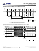
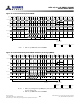
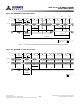


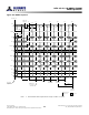
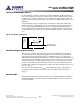
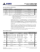
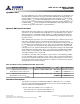
Table Of Contents
- DDR3L SDRAM
- Description
- State Diagram
- Functional Description
- Functional Block Diagrams
- Ball Assignments and Descriptions
- Package Dimensions
- Electrical Specifications
- Thermal Characteristics
- Electrical Specifications – I DD Specifications and Conditions
- Electrical Characteristics – 1.35V IDD Specifications
- Electrical Specifications – DC and AC
- ODT Characteristics
- Output Driver Impedance
- Output Characteristics and Operating Conditions
- Speed Bin Tables
- Electrical Characteristics and AC Operating Conditions
- Electrical Characteristics and AC Operating Conditions
- Command and Address Setup, Hold, and Derating
- Data Setup, Hold, and Derating
- Commands – Truth Tables
- Commands
- Input Clock Frequency Change
- Write Leveling
- Initialization
- Voltage Initialization / Change
- Mode Registers
- Mode Register 0 (MR0)
- Mode Register 1 (MR1)
- Mode Register 2 (MR2)
- Mode Register 3 (MR3)
- MODE REGISTER SET (MRS) Command
- ZQ CALIBRATION Operation
- ACTIVATE Operation
- READ Operation
- WRITE Operation
- PRECHARGE Operation
- SELF REFRESH Operation
- Extended Temperature Usage
- Power-Down Mode
- RESET Operation
- On-Die Termination (ODT)
- Dynamic ODT
- Synchronous ODT Mode
- Asynchronous ODT Mode
- Asynchronous to Synchronous ODT Mode Transition (Power-Down Exit)

Dynamic ODT
In certain application cases, and to further enhance signal integrity on the data bus, it is
desirable that the termination strength of the DDR3 SDRAM can be changed without
issuing an MRS command, essentially changing the ODT termination on the fly. With
dynamic ODT R
TT(WR)
) enabled, the DRAM switches from nominal ODT R
TT,nom
) to dy-
namic ODT R
TT(WR)
) when beginning a WRITE burst and subsequently switches back to
nominal ODT R
TT,nom
) at the completion of the WRITE burst. This requirement is sup-
ported by the dynamic ODT feature, as described below.
Dynamic ODT Special Use Case
When DDR3 devices are architect as a single rank memory array, dynamic ODT offers a
special use case: the ODT ball can be wired high (via a current limiting resistor prefer-
red) by having R
TT,nom
disabled via MR1 and R
TT(WR)
enabled via MR2. This will allow
the ODT signal not to have to be routed yet the DRAM can provide ODT coverage dur-
ing write accesses.
When enabling this special use case, some standard ODT spec conditions may be viola-
ted: ODT is sometimes suppose to be held low. Such ODT spec violation (ODT not
LOW) is allowed under this special use case. Most notably, if Write Leveling is used, this
would appear to be a problem since R
TT(WR)
can not be used (should be disabled) and
R
TT(NOM)
should be used. For Write leveling during this special use case, with the DLL
locked, then R
TT(NOM)
maybe enabled when entering Write Leveling mode and disabled
when exiting Write Leveling mode. More so, R
TT(NOM)
must be enabled when enabling
Write Leveling, via same MR1 load, and disabled when disabling Write Leveling, via
same MR1 load if R
TT(NOM)
is to be used.
ODT will turn-on within a delay of ODTLon +
t
AON +
t
MOD + 1CK (enabling via MR1)
or turn-off within a delay of ODTLoff +
t
AOF +
t
MOD + 1CK. As seen in the table below,
between the Load Mode of MR1 and the previously specified delay, the value of ODT is
uncertain. this means the DQ ODT termination could turn-on and then turn-off again
during the period of stated uncertainty.
Table 82: Write Leveling with Dynamic ODT Special Case
Begin R
TT,nom
Uncertainty End R
TT,nom
Uncertainty I/Os R
TT,nom
Final State
MR1 load mode command:
Enable Write Leveling and R
TT(NOM)
ODTLon +
t
AON +
t
MOD + 1CK DQS, DQS# Drive R
TT,nom
value
DQs No R
TT,nom
MR1 load mode command:
Disable Write Leveling and R
TT(NOM)
ODTLoff +
t
AOFF +
t
MOD + 1CK DQS, DQS# No R
TT,nom
DQs No R
TT,nom
Functional Description
The dynamic ODT mode is enabled if either MR2[9] or MR2[10] is set to 1. Dynamic
ODT is not supported during DLL disable mode so R
TT(WR)
must be disabled. The dy-
namic ODT function is described below:
• Two R
TT
values are available—R
TT,nom
and R
TT(WR)
.
– The value for R
TT,nom
is preselected via MR1[9, 6, 2].
– The value for R
TT(WR)
is preselected via MR2[10, 9].
8Gb: x4, x8, x16 DDR3L SDRAM
Dynamic ODT
189
Rev.2.0 June 2016
© 2015 Alliance Memory, Inc. All rights reserved.
Alliance Memory Inc. reserves the right to change products or specification without notice
Alliance Memory Inc. 511 Taylor Way, San Carlos, CA 94070
TEL: (650) 610-6800 FAX: (650) 620-9211