
Datasheet
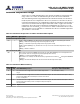

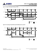
Table Of Contents
- DDR3L SDRAM
- Description
- State Diagram
- Functional Description
- Functional Block Diagrams
- Ball Assignments and Descriptions
- Package Dimensions
- Electrical Specifications
- Thermal Characteristics
- Electrical Specifications – I DD Specifications and Conditions
- Electrical Characteristics – 1.35V IDD Specifications
- Electrical Specifications – DC and AC
- ODT Characteristics
- Output Driver Impedance
- Output Characteristics and Operating Conditions
- Speed Bin Tables
- Electrical Characteristics and AC Operating Conditions
- Electrical Characteristics and AC Operating Conditions
- Command and Address Setup, Hold, and Derating
- Data Setup, Hold, and Derating
- Commands – Truth Tables
- Commands
- Input Clock Frequency Change
- Write Leveling
- Initialization
- Voltage Initialization / Change
- Mode Registers
- Mode Register 0 (MR0)
- Mode Register 1 (MR1)
- Mode Register 2 (MR2)
- Mode Register 3 (MR3)
- MODE REGISTER SET (MRS) Command
- ZQ CALIBRATION Operation
- ACTIVATE Operation
- READ Operation
- WRITE Operation
- PRECHARGE Operation
- SELF REFRESH Operation
- Extended Temperature Usage
- Power-Down Mode
- RESET Operation
- On-Die Termination (ODT)
- Dynamic ODT
- Synchronous ODT Mode
- Asynchronous ODT Mode
- Asynchronous to Synchronous ODT Mode Transition (Power-Down Exit)
Power-Down Mode
Power-down is synchronously entered when CKE is registered LOW coincident with a
NOP or DES command. CKE is not allowed to go LOW while an MRS, MPR, ZQCAL,
READ, or WRITE operation is in progress. CKE is allowed to go LOW while any of the
other legal operations (such as ROW ACTIVATION, PRECHARGE, auto precharge, or RE-
FRESH) are in progress. However, the power-down I
DD
specifications are not applicable
until such operations have completed. Depending on the previous DRAM state and the
command issued prior to CKE going LOW, certain timing constraints must be satisfied
(as noted in Table 78). Timing diagrams detailing the different power-down mode entry
and exits are shown in Figure 94 (page 179) through Figure 103 (page 183).
Table 78: Command to Power-Down Entry Parameters
DRAM Status
Last Command Prior to
CKE LOW
1
Parameter (Min) Parameter Value Figure
Idle or active ACTIVATE
t
ACTPDEN 1
t
CK Figure 101 (page 182)
Idle or active PRECHARGE
t
PRPDEN 1
t
CK Figure 102 (page 183)
Active READ or READAP
t
RDPDEN RL + 4
t
CK + 1
t
CK Figure 97 (page 180)
Active WRITE: BL8OTF, BL8MRS,
BC4OTF
t
WRPDEN WL + 4
t
CK +
t
WR/
t
CK Figure 98 (page 181)
Active WRITE: BC4MRS WL + 2
t
CK +
t
WR/
t
CK Figure 98 (page 181)
Active WRITEAP: BL8OTF, BL8MRS,
BC4OTF
t
WRAPDEN WL + 4
t
CK + WR + 1
t
CK Figure 99 (page 181)
Active WRITEAP: BC4MRS WL + 2
t
CK + WR + 1
t
CK Figure 99 (page 181)
Idle REFRESH
t
REFPDEN 1
t
CK Figure 100 (page 182)
Power-down REFRESH
t
XPDLL Greater of 10
t
CK or 24ns Figure 104 (page 184)
Idle MODE REGISTER SET
t
MRSPDEN
t
MOD Figure 103 (page 183)
Note:
1. If slow-exit mode precharge power-down is enabled and entered, ODT becomes asyn-
chronous
t
ANPD prior to CKE going LOW and remains asynchronous until
t
ANPD +
t
XPDLL after CKE goes HIGH.
Entering power-down disables the input and output buffers, excluding CK, CK#, ODT,
CKE, and RESET#. NOP or DES commands are required until
t
CPDED has been satis-
fied, at which time all specified input/output buffers are disabled. The DLL should be in
a locked state when power-down is entered for the fastest power-down exit timing. If
the DLL is not locked during power-down entry, the DLL must be reset after exiting
power-down mode for proper READ operation as well as synchronous ODT operation.
During power-down entry, if any bank remains open after all in-progress commands are
complete, the DRAM will be in active power-down mode. If all banks are closed after all
in-progress commands are complete, the DRAM will be in precharge power-down
mode. Precharge power-down mode must be programmed to exit with either a slow exit
mode or a fast exit mode. When entering precharge power-down mode, the DLL is
turned off in slow exit mode or kept on in fast exit mode.
The DLL also remains on when entering active power-down. ODT has special timing
constraints when slow exit mode precharge power-down is enabled and entered. Refer
to Asynchronous ODT Mode (page 200) for detailed ODT usage requirements in slow
8Gb: x4, x8, x16 DDR3L SDRAM
Power-Down Mode
177
Rev.2.0 June 2016
© 2015 Alliance Memory, Inc. All rights reserved.
Alliance Memory Inc. reserves the right to change products or specification without notice
Alliance Memory Inc. 511 Taylor Way, San Carlos, CA 94070
TEL: (650) 610-6800 FAX: (650) 620-9211