
Datasheet
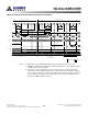
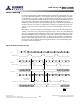
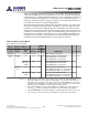
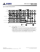

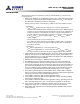

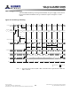
Table Of Contents
- DDR3L SDRAM
- Description
- State Diagram
- Functional Description
- Functional Block Diagrams
- Ball Assignments and Descriptions
- Package Dimensions
- Electrical Specifications
- Thermal Characteristics
- Electrical Specifications – I DD Specifications and Conditions
- Electrical Characteristics – 1.35V IDD Specifications
- Electrical Specifications – DC and AC
- ODT Characteristics
- Output Driver Impedance
- Output Characteristics and Operating Conditions
- Speed Bin Tables
- Electrical Characteristics and AC Operating Conditions
- Electrical Characteristics and AC Operating Conditions
- Command and Address Setup, Hold, and Derating
- Data Setup, Hold, and Derating
- Commands – Truth Tables
- Commands
- Input Clock Frequency Change
- Write Leveling
- Initialization
- Voltage Initialization / Change
- Mode Registers
- Mode Register 0 (MR0)
- Mode Register 1 (MR1)
- Mode Register 2 (MR2)
- Mode Register 3 (MR3)
- MODE REGISTER SET (MRS) Command
- ZQ CALIBRATION Operation
- ACTIVATE Operation
- READ Operation
- WRITE Operation
- PRECHARGE Operation
- SELF REFRESH Operation
- Extended Temperature Usage
- Power-Down Mode
- RESET Operation
- On-Die Termination (ODT)
- Dynamic ODT
- Synchronous ODT Mode
- Asynchronous ODT Mode
- Asynchronous to Synchronous ODT Mode Transition (Power-Down Exit)

When write leveling is enabled, the rising edge of DQS samples CK, and the prime DQ
outputs the sampled CK’s status. The prime DQ for a x4 or x8 configuration is DQ0 with
all other DQ (DQ[7:1]) driving LOW. The prime DQ for a x16 configuration is DQ0 for the
lower byte and DQ8 for the upper byte. It outputs the status of CK sampled by LDQS
and UDQS. All other DQ (DQ[7:1], DQ[15:9]) continue to drive LOW. Two prime DQ on a
x16 enable each byte lane to be leveled independently.
The write leveling mode register interacts with other mode registers to correctly config-
ure the write leveling functionality. Besides using MR1[7] to disable/enable write level-
ing, MR1[12] must be used to enable/disable the output buffers. The ODT value, burst
length, and so forth need to be selected as well. This interaction is shown in Table 72. It
should also be noted that when the outputs are enabled during write leveling mode, the
DQS buffers are set as inputs, and the DQ are set as outputs. Additionally, during write
leveling mode, only the DQS strobe terminations are activated and deactivated via the
ODT ball. The DQ remain disabled and are not affected by the ODT ball.
Table 72: Write Leveling Matrix
Note 1 applies to the entire table
MR1[7] MR1[12] MR1[2, 6, 9]
DRAM
ODT Ball
DRAM
R
TT,nom
DRAM State Case Notes
Write
Leveling
Output
Buffers
R
TT,nom
Value DQS DQ
Disabled See normal operations Write leveling not enabled 0
Enabled
(1)
Disabled
(1)
n/a Low Off Off DQS not receiving: not terminated
Prime DQ High-Z: not terminated
Other DQ High-Z: not terminated
12
ΩΩ
ΩΩ, or
120Ω
High On DQS not receiving: terminated by R
TT
Prime DQ High-Z: not terminated
Other DQ High-Z: not terminated
2
Enabled
(0)
n/a Low Off DQS receiving: not terminated
Prime DQ driving CK state: not terminated
Other DQ driving LOW: not terminated
33
ΩΩ, or
120Ω
High On DQS receiving: terminated by R
TT
Prime DQ driving CK state: not terminated
Other DQ driving LOW: not terminated
4
Notes:
1. Expected usage if used during write leveling: Case 1 may be used when DRAM are on a
dual-rank module and on the rank not being leveled or on any rank of a module not
being leveled on a multislot system. Case 2 may be used when DRAM are on any rank of
a module not being leveled on a multislot system. Case 3 is generally not used. Case 4 is
generally used when DRAM are on the rank that is being leveled.
2. Since the DRAM DQS is not being driven (MR1[12] = 1), DQS ignores the input strobe,
and all R
TT,nom
values are allowed. This simulates a normal standby state to DQS.
3. Since the DRAM DQS is being driven (MR1[12] = 0), DQS captures the input strobe, and
only some R
TT,nom
values are allowed. This simulates a normal write state to DQS.
8Gb: x4, x8, x16 DDR3L SDRAM
Write Leveling
122
Rev 2.0 June 2016
© 2015 Alliance Memory, Inc. All rights reserved.
Alliance Memory Inc. reserves the right to change products or specification without notice
Alliance Memory Inc. 511 Taylor Way, San Carlos, CA 94070
TEL: (650) 610-6800 FAX: (650) 620-9211