
Datasheet
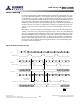
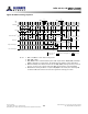


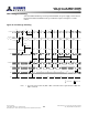
Table Of Contents
- DDR3L SDRAM
- Description
- State Diagram
- Functional Description
- Functional Block Diagrams
- Ball Assignments and Descriptions
- Package Dimensions
- Electrical Specifications
- Thermal Characteristics
- Electrical Specifications – I DD Specifications and Conditions
- Electrical Characteristics – 1.35V IDD Specifications
- Electrical Specifications – DC and AC
- ODT Characteristics
- Output Driver Impedance
- Output Characteristics and Operating Conditions
- Speed Bin Tables
- Electrical Characteristics and AC Operating Conditions
- Electrical Characteristics and AC Operating Conditions
- Command and Address Setup, Hold, and Derating
- Data Setup, Hold, and Derating
- Commands – Truth Tables
- Commands
- Input Clock Frequency Change
- Write Leveling
- Initialization
- Voltage Initialization / Change
- Mode Registers
- Mode Register 0 (MR0)
- Mode Register 1 (MR1)
- Mode Register 2 (MR2)
- Mode Register 3 (MR3)
- MODE REGISTER SET (MRS) Command
- ZQ CALIBRATION Operation
- ACTIVATE Operation
- READ Operation
- WRITE Operation
- PRECHARGE Operation
- SELF REFRESH Operation
- Extended Temperature Usage
- Power-Down Mode
- RESET Operation
- On-Die Termination (ODT)
- Dynamic ODT
- Synchronous ODT Mode
- Asynchronous ODT Mode
- Asynchronous to Synchronous ODT Mode Transition (Power-Down Exit)
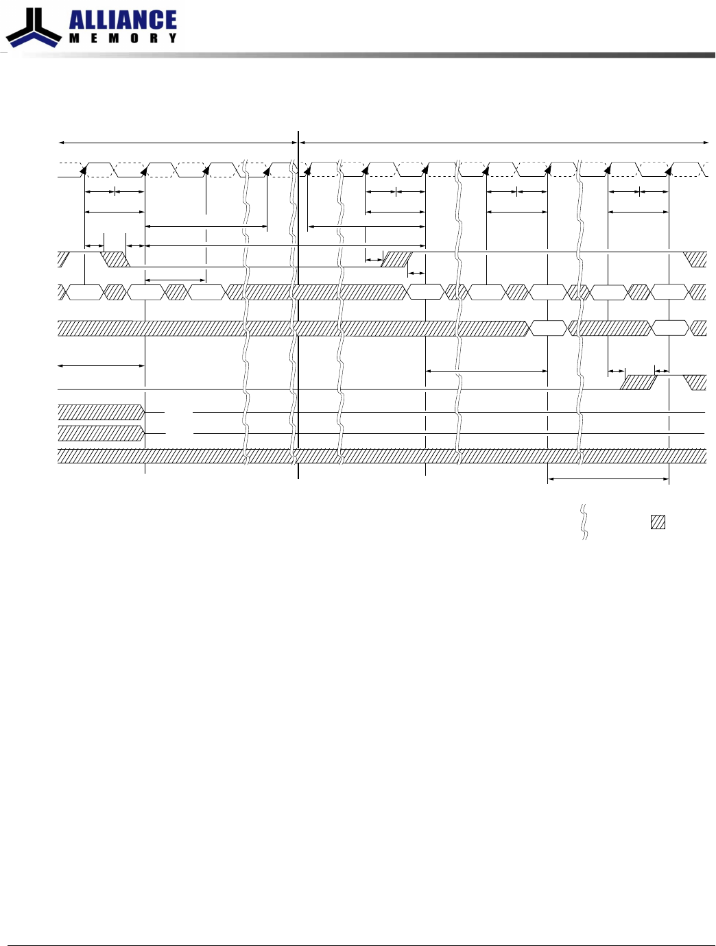
Figure 42: Change Frequency During Precharge Power-Down
CK
CK#
Command
NOPNOPNOP
Address
CKE
DQ
DM
DQS, DQS#
NOP
t
CK
Enter precharge
power-down mode
Exit precharge
power-down mode
T0 T1 Ta0 Tc0Tb0T2
Don’t Care
t
CKE
t
XP
MRS
DLL RESET
Valid
Valid
NOP
t
CH
t
IH
t
IS
t
CL
Tc1 Td0 Te1Td1
t
CKSRE
t
CH
b
t
CL
b
t
CK
b
t
CH
b
t
CL
b
t
CK
b
t
CH
b
t
CL
b
t
CK
b
t
CPDED
ODT
NOP
Te0
Previous clock frequency New clock frequency
Frequency
change
Indicates break
in time scale
t
IH
t
IS
t
IH
t
IS
t
DLLK
t
AOFPD/
t
AOF
t
CKSRX
High-Z
High-Z
Notes:
1. Applicable for both SLOW-EXIT and FAST-EXIT precharge power-down modes.
2.
t
AOFPD and
t
AOF must be satisfied and outputs High-Z prior to T1 (see On-Die Termina-
tion (ODT) for exact requirements).
3. If the R
TT,nom
feature was enabled in the mode register prior to entering precharge
power-down mode, the ODT signal must be continuously registered LOW, ensuring R
TT
is in an off state. If the R
TT,nom
feature was disabled in the mode register prior to enter-
ing precharge power-down mode, R
TT
will remain in the off state. The ODT signal can
be registered LOW or HIGH in this case.
8Gb: x4, x8, x16 DDR3L SDRAM
Input Clock Frequency Change
120
Rev 2.0 June 2016
© 2015 Alliance Memory, Inc. All rights reserved.
Alliance Memory Inc. reserves the right to change products or specification without notice
Alliance Memory Inc. 511 Taylor Way, San Carlos, CA 94070
TEL: (650) 610-6800 FAX: (650) 620-9211