
Datasheet

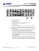
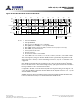

Table Of Contents
- DDR3L SDRAM
- Description
- State Diagram
- Functional Description
- Functional Block Diagrams
- Ball Assignments and Descriptions
- Package Dimensions
- Electrical Specifications
- Thermal Characteristics
- Electrical Specifications – I DD Specifications and Conditions
- Electrical Characteristics – 1.35V IDD Specifications
- Electrical Specifications – DC and AC
- ODT Characteristics
- Output Driver Impedance
- Output Characteristics and Operating Conditions
- Speed Bin Tables
- Electrical Characteristics and AC Operating Conditions
- Electrical Characteristics and AC Operating Conditions
- Command and Address Setup, Hold, and Derating
- Data Setup, Hold, and Derating
- Commands – Truth Tables
- Commands
- Input Clock Frequency Change
- Write Leveling
- Initialization
- Voltage Initialization / Change
- Mode Registers
- Mode Register 0 (MR0)
- Mode Register 1 (MR1)
- Mode Register 2 (MR2)
- Mode Register 3 (MR3)
- MODE REGISTER SET (MRS) Command
- ZQ CALIBRATION Operation
- ACTIVATE Operation
- READ Operation
- WRITE Operation
- PRECHARGE Operation
- SELF REFRESH Operation
- Extended Temperature Usage
- Power-Down Mode
- RESET Operation
- On-Die Termination (ODT)
- Dynamic ODT
- Synchronous ODT Mode
- Asynchronous ODT Mode
- Asynchronous to Synchronous ODT Mode Transition (Power-Down Exit)

DLL Disable Mode
If the DLL is disabled by the mode register (MR1[0] can be switched during initialization
or later), the DRAM is targeted, but not guaranteed, to operate similarly to the normal
mode, with a few notable exceptions:
• The DRAM supports only one value of CAS latency (CL = 6) and one value of CAS
WRITE latency (CWL = 6).
• DLL disable mode affects the read data clock-to-data strobe relationship (
t
DQSCK),
but not the read data-to-data strobe relationship (
t
DQSQ,
t
QH). Special attention is
required to line up the read data with the controller time domain when the DLL is dis-
abled.
• In normal operation (DLL on),
t
DQSCK starts from the rising clock edge AL + CL
cycles after the READ command. In DLL disable mode,
t
DQSCK starts AL + CL - 1 cy-
cles after the READ command. Additionally, with the DLL disabled, the value of
t
DQSCK could be larger than
t
CK.
The ODT feature (including dynamic ODT) is not supported during DLL disable mode.
The ODT resistors must be disabled by continuously registering the ODT ball LOW by
programming R
TT,nom
MR1[9, 6, 2] and R
TT(WR)
MR2[10, 9] to 0 while in the DLL disable
mode.
Specific steps must be followed to switch between the DLL enable and DLL disable
modes due to a gap in the allowed clock rates between the two modes (
t
CK [AVG] MAX
and
t
CK [DLL_DIS] MIN, respectively). The only time the clock is allowed to cross this
clock rate gap is during self refresh mode. Thus, the required procedure for switching
from the DLL enable mode to the DLL disable mode is to change frequency during self
refresh:
1. Starting from the idle state (all banks are precharged, all timings are fulfilled, ODT
is turned off, and R
TT,nom
and R
TT(WR)
are High-Z), set MR1[0] to 1 to disable the
DLL.
2. Enter self refresh mode after
t
MOD has been satisfied.
3. After
t
CKSRE is satisfied, change the frequency to the desired clock rate.
4. Self refresh may be exited when the clock is stable with the new frequency for
t
CKSRX. After
t
XS is satisfied, update the mode registers with appropriate values.
5. The DRAM will be ready for its next command in the DLL disable mode after the
greater of
t
MRD or
t
MOD has been satisfied. A ZQCL command should be issued
with appropriate timings met.
8Gb: x4, x8, x16 DDR3L SDRAM
Commands
115
Rev 2.0 June 2016
© 2015 Alliance Memory, Inc. All rights reserved.
Alliance Memory Inc. reserves the right to change products or specification without notice
Alliance Memory Inc. 511 Taylor Way, San Carlos, CA 94070
TEL: (650) 610-6800 FAX: (650) 620-9211