
Datasheet


Table Of Contents
CAS Latency Field (A6~A4)
This field specifies the number of clock cycles from the assertion of the Read command to the first read
whole value satisfying the following formula must be programmed into this field.
t
CAC
(min) CAS Latency X t
CK
Table 9. CAS latency Field
A6
A5
A4
CAS Latency
0
0
0
Reserved
0
0
1
Reserved
0
1
0
2 clocks
0
1
1
3 clocks
1
X
X
Reserved
Test Mode field (A8~A7)
These two bits are used to enter the test mode and must be programmed to "00" in normal operation.
Table 10. Test Mode Field
A8
A7
Test Mode
0
0
Normal mode
0
1
Vendor Use Only
1
X
Vendor Use Only
Write Burst Length (A9)
This bit is used to select the write burst mode. When the A9 bit is "0", the Burst-Read-Burst-Write mode
is selected. When the A9 bit is "1", the Burst-Read-Single-Write mode is selected.
Table 11. Write Burst Length
A9
Write Burst Mode
0
Burst-Read-Burst-Write
1
Burst-Read-Single-Write
Note: A10 and BA0, 1 should stay “L” during mode set cycle.
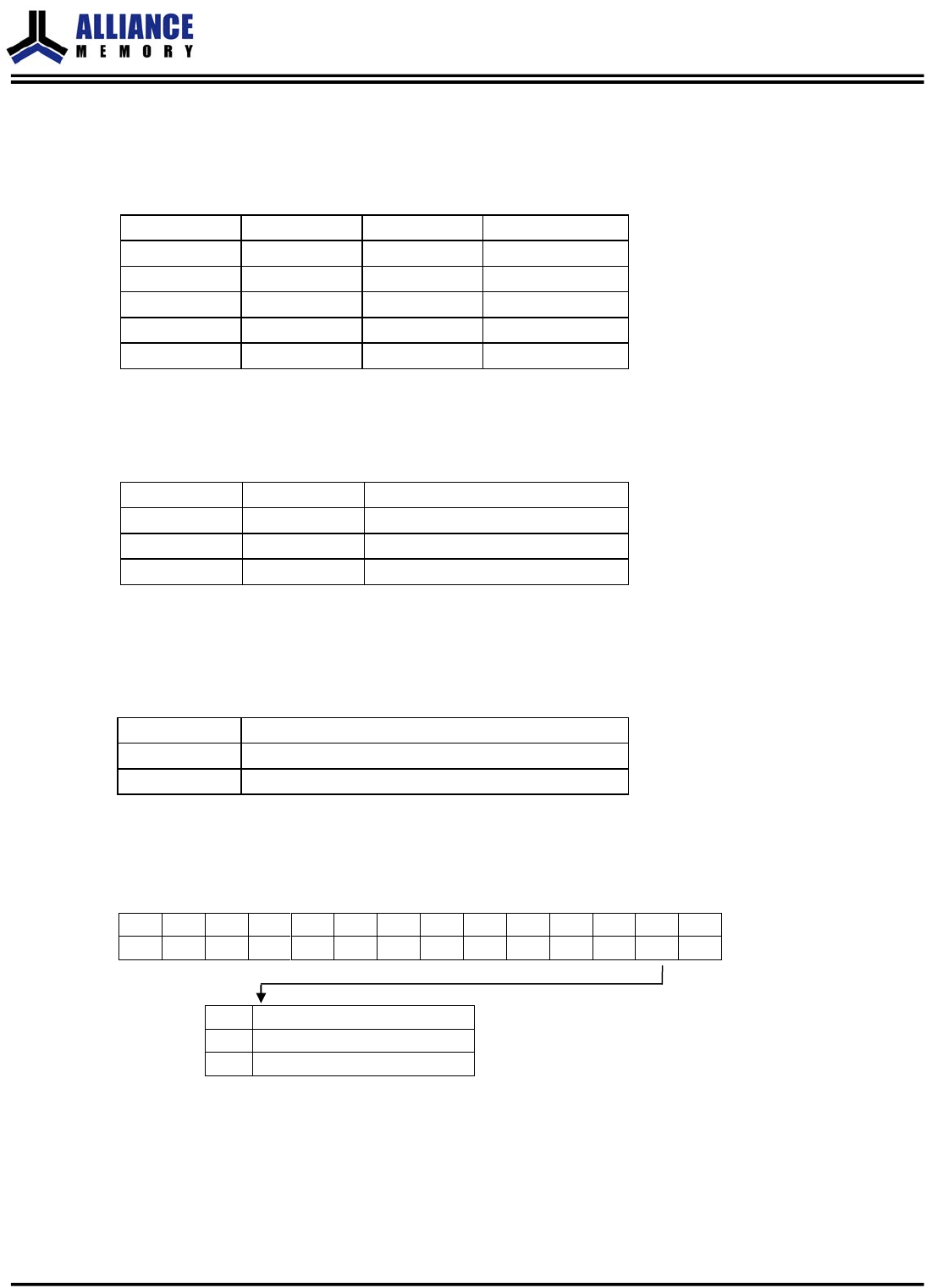
Extended Mode Register Bitmap
Table 12.Extended Mode Register Bitmap
BA1
BA0
A11
A10
A9
A8
A7
A6
A5
A4
A3
A2
A1
A0
Address Field
0
1
0
0
0
0
0
0
0
0
0
0
DS
0
Extended Mode Register
A1
Drive Strength
0
Full
1
Weak
AS4C4M16SA-C&I
Confidential
- 15 of 56 -
Rev.5.0 October 2018