
Datasheet


AS4C32M16D1A-C&I
3
Rev. 1.0 Mar. /2015
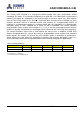
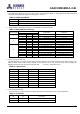
Operation Mode
Table 3 shows the truth table for the operation commands.
Table 3. Truth Table (Note (1), (2))
Command
State
CKE
n-1
CKE
n
DM
BA0,1
A10
A0-9, 11-12
CS
RAS
CAS
WE
BankActivate
Idle
(3)
H
X
X
V
Row address
L
L
H
H
BankPrecharge
Any
H
X
X
V
L
X
L
L
H
L
PrechargeAll
Any
H
X
X
X
H
X
L
L
H
L
Write
Active
(3)
H
X
X
V
L
Column
address
(A0 ~ A9)
L
H
L
L
Write and AutoPrecharge
Active
(3)
H
X
X
V
H
L
H
L
L
Read
Active
(3)
H
X
X
V
L
Column
address
(A0 ~ A9)
L
H
L
H
Read and Autoprecharge
Active
(3)
H
X
X
V
H
L
H
L
H
Mode Register Set
Idle
H
X
X
OP code
L
L
L
L
Extended MRS
Idle
H
X
X
OP code
L
L
L
L
No-Operation
Any
H
X
X
X
X
X
L
H
H
H
Burst Stop
Active
(4)
H
X
X
X
X
X
L
H
H
L
Device Deselect
Any
H
X
X
X
X
X
H
X
X
X
AutoRefresh
Idle
H
H
X
X
X
X
L
L
L
H
SelfRefresh Entry
Idle
H
L
X
X
X
X
L
L
L
H
SelfRefresh Exit
Idle
L
H
X
X
X
X
H
X
X
X
(SelfRefresh)
L
H
H
H
Precharge Power Down Mode Entry
Idle
H
L
X
X
X
X
H
X
X
X
L
H
H
H
Precharge Power Down Mode Exit
Any
L
H
X
X
X
X
H
X
X
X
(PowerDown)
L
H
H
H
Active Power Down Mode Entry
Active
H
L
X
X
X
X
H
X
X
X
L
V
V
V
Active Power Down Mode Exit
Any
L
H
X
X
X
X
H
X
X
X
(PowerDown)
L
H
H
H
Data Input Mask Disable
Active
H
X
L
X
X
X
X
X
X
X
Data Input Mask Enable(5)
Active
H
X
H
X
X
X
X
X
X
X
Note: 1. V=Valid data, X=Don't Care, L=Low level, H=High level
2. CKE
n
signal is input level when commands are provided.
CKE
n-1
signal is input level one clock cycle before the commands are provided.
3. These are states of bank designated by BA signal.
4. Device state is 2, 4, and 8 burst operation.
5. LDM and UDM can be enabled respectively.