
Datasheet


AS4C32M16D1A-C&I
47
Rev. 1.0 Mar. /2015
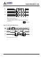
Figure 32. Initialize and Mode Register Sets
t
IS
t
IH
NOP PRE
EMRS
MRS PRE AR
AR MRS
ACT
CODE
CODE
CODE
RA
tVDT>=0
t
CH
t
CL
t
CK
t
IS
t
IH
t
IS
t
IH
CODE
CODE
CODE
RA
t
IS
t
IH
t
IS
t
IH
ALL BANKS
t
IS
t
IH
ALL BANKS
BA0=H
BA1=L
BA0=L
BA1=L
BA0=L
BA1=L
BA
t
IS
t
IH
High-Z
High-Z
LVCMOS LOW LEVEL
CK
CK
DM
A0-A9,
A11,A12
COMMAND
VREF
CKE
A10
BA0,BA1
DQS
DQ
VDD
VDDQ
VTT
(system*)
*=VTT is not applied directly to the device, however tVTD must be greater than or equal to zero to avoid device latch-up.
** = tMRD is required before any command can be applied, and 200 cycles of CK are required before any executable
command can be applied the two auto Refresh commands may be moved to follow the first MRS but precede the second
PRECHARGE ALL command.
Don’t Care
Power-up:
VDD and
CLK stable
Extended mode
Register set
Load Mode
Register,
Reset DLL (with A8=H)
200 cycles of CK**
Load Mode
Register,
(with A8=L)
T=200µs
**t
MRD
**t
MRD
t
RFC
t
RFC
**t
MRD
t
RP