
Datasheet


Notes:
1.
16-word burst length is optional.
2.
For a burst length of two, A1-An selects the two data element block; A0 selects the first access within the block.
3.
For a burst length of four, A2-An selects the four data element block; A0-A1 selects the first access within the block.
4.
For a burst length of eight, A3-An selects the eight data element block; A0-A2 selects the first access within the block.
5.
For the optional burst length of sixteen, A4-An selects the sixteen data element block; A0-A3 selects the first access within the block.
6.
Whenever a boundary of the block is reached within a given sequence, the following access wraps within the block
When a READ or WRITE command is issued, a block of columns equal to the burst length is effectively selected. All accesses
for that burst take place within the block, meaning that the burst will wrap within the block if a boundary is reached.
The block is uniquely selected by
A1-An when the burst length is set to two, by A2-An when the burst length is set to 4, by A3-An
when the burst length is set to 8 and A4-An when the burst length is set to 16 (where An is the most significant column address
bit for a given configuration). The remaining (least significant) address bit(s) is (are) used to select the starting location within the
block. The programmed burst length applies to both read and write bursts.
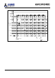
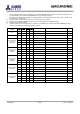
5.2.1.2 Burst Type
Accesses within a given burst may be programmed to be either sequential or interleaved; this is referred to as the burst type and
is selected via bit A3.
The ordering of accesses within a b
urst is determined by the burst length, the burst type and the starting column address, as
shown in Table 4.
5.2.1.3 Read Latency
The READ latency, or CAS latency, is the delay between the registration of a READ command and the availability of the first
piece of output data. The latency should be set to 3 clocks. Some vendors may offer additional options of 2 clocks and/or 4
clocks.
If a READ command is registered at a clock edge n and the latency is 3 clocks, the first data element will be valid at n + 2t
CK +
t
AC. If a READ command is registered at a clock edge n and the latency is 2 clocks, the first data element will be valid at n + tCK
+ tAC. Lastly, if a READ command is registered at a clock edge n and the latency is 4 clocks, the first data element will be valid
at n + 3t
CK + tAC.
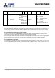
5.2.2 Extended Mode Register
The Extended Mode Register controls functions beyond those controlled by the Mode Register; these additional functions
include output drive strength selection, Temperature Compensated Self Refresh (TCSR) and Partial Array Self Refresh (PASR),
as shown in Figure 7. The TCSR and PASR functions are optional and some vendors may choose not to implement them. Both
TCSR and PASR are effective is in Self Refresh mode only.
The Extended Mode Register is programmed via the MODE REGISTER SET command (with BA1=1 and BA0=0) and will retain
the stored information until it is reprogrammed, the device is put in Deep Power-Down mode, or the device loses power.
The Extended Mode Register must be loaded
when all banks are idle and no bursts are in progress, and the controller must wait
the specified time t
MRD before initiating any subsequent operation. Violating either of these requirements will result in
unspecified operation.
Address bits A0-A2 specify PASR, A3-A4 the TCSR, A5-A6 the Drive Strength. A logic 0 should be programmed to all the
undefined addresses bits to ensure future compatibility.
Reserved states should not be used, as unknown operation or incompatibility with future versions may result.
Address bits A0-A2 specify PASR, A3-A4 the TCSR, A5-A7 the Drive Strength.
A logic 0 should be programme
d to all the undefined address bits to ensure future compatibility.
Reserved states should not be used, as unknown operation or incompatibility with future versions may result.
AS4C16M16MD1
256Mb MOBILE DDR SDRAM
Confidential
- 15/56 -
Ver.1.1 Oct.2015