Installation Washer-Extractors Pocket Hardmount Variable-Speed WE-6 Control Refer to Page 6 for Model Numbers 1 2 3 5 6 7 8 9 1 0 4 PHM1389 PHM1 PHM1389C UW35PV – UW125PV PHM1390CN PHM1390C UW150PV Para bajar una copia de estas instrucciones en español, visite www.comlaundry.com. Keep These Instructions for Future Reference. (If this machine changes ownership, this manual must accompany machine.) www.comlaundry.com Part No.
Table of Contents Safety Information.............................................................................. Explanation of Safety Messages........................................................... Important Safety Instructions ............................................................... Safety Decals ........................................................................................ Operator Safety.....................................................................................
Safety Information Explanation of Safety Messages Precautionary statements (“DANGER,” “WARNING,” and “CAUTION”), followed by specific instructions, are found in this manual and on machine decals. These precautions are intended for the personal safety of the operator, user, servicer, and those maintaining the machine.
Safety Information 9. Do not install or store the washer where it will be exposed to water and/or weather. 10. Do not tamper with the controls. 11. Do not repair or replace any part of the washer, or attempt any servicing unless specifically recommended in the user-maintenance instructions or in published user-repair instructions that the user understands and has the skills to carry out. 12.
Safety Information WARNING CAUTION This machine must be installed, adjusted, and serviced by qualified electrical maintenance personnel familiar with the construction and operation of this type of machinery. They must also be familiar with the potential hazards involved. Failure to observe this warning may result in personal injury and/or equipment damage, and may void the warranty. SW004 IMPORTANT: Ensure that the recommended clearaces for inspection and maintenance are provided.
Safety Information Operator Safety Do not bypass any safety devices in the machine. WARNING WARNING NEVER insert hands or objects into basket until it has completely stopped. Doing so could result in serious injury. SW012 To ensure the safety of machine operators, the following maintenance checks must be performed daily: Never operate the machine with a bypassed or disconnected balance system.
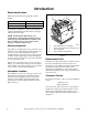
Introduction Model Identification Information in this manual is applicable to these models: MODEL EXAMPLE OF NAMEPLATE LOCATION 3 1 UW35PV UW60PV UW80PV UW100PV UW125PV UW150PV 2 This manual is designed as a guide to the installation of the Pocket Hardmount washer-extractor equipped with the AC inverter drive. P U S H NOTE: All information, illustrations, and specifications contained in this manual are based on the latest product information available at the time of printing.
Introduction Model Number Familiarization Guide Sample Model Number: UW60PVQU80001 UW Model Number Prefix 60 Washer-Extractor Capacity (pounds dry weight of laundry) P Type of Electrical Control P = WE-6 Computer V Washer-Extractor Speed Capabilities V = 7 Speeds Q Electrical Characteristics Refer to Table 7.
Specifications and Dimensions . UWPV Models Specifications 35 60 80 100 125 150 Overall width, in (mm) 32.5 (826) 36.63 (930) 41.5 (1054) 41.5 (1054) 48 (1219) 50.25 (1277) Overall height, in (mm) 55.5 (1410) 64.5 (1638) 68.5 (1740) 68.5 (1740) 72 (1829) 79 (2007) Overall depth, in (mm) 43.63 (1108) 45 (1143) 51.5 (1308) 54.
Specifications and Dimensions UWPV Models (Continued) Specifications 35 60 80 100 125 150 Cylinder Speeds / Centrifugal Force Data 1/2 Wash/reverse, rpm (g) 26 (.25) 26 (.31) 26 (.35) 26 (.35) 26 (.40) 23 (.31) Wash/reverse, rpm (g) 42 (.66) 40 (.73) 40 (.82) 40 (.82) 37 (.82) 36 (0.8) Distribution, rpm (g) 83 (2.57) 71 (2.29) 73 (2.57) 70 (2.50) 62 (2.29) 61 (2.
Specifications and Dimensions Direct Steam Heating (Optional) Steam inlet connection size, in (mm) 1/2 (13) 1/2 (13) 1/2 (13) 1/2 (13) 3/4 (19) 3/4 (19) 1 1 1 1 1 1 LO W 2.1 (1.5) 3.3 (2.4) 4.6 (3.3) 5.7 (4.1) 6.7 (4.9) 8.3 (6.0) ME D 2.3 (1.7) 3.7 (2.6) 5.2 (3.8) 6.5 (4.7) 7.8 (5.6) 9.5 (6.9) HIG H 2.7 (1.9) 4.1 (2.9) 6.1 (4.4) 7.6 (5.5) 9.1 (6.6) 11.1 (8.0) 1.4 (21.4) 2.1 (33.4) 3.1 (48.4) 3.8 (60.4) 4.6 (72.0) 5.8 (91.0) 15.6 25.2 37.8 37.8 50.
Specifications and Dimensions Machine Dimensions Dimensional Clearances Allow a minimum of 24 inches (60 cm) at the rear and 18 inches (45 cm) at the sides for maintenance, inspection, and adjustment. Allow at least 18 inches (45 cm) between machines in multiple installations. Machine dimensions are indicated in Figure 3, Figure 4 and Table 1. exact dimensions are required for construction purposes, contact the distributor or the manufacturer.
Specifications and Dimensions 1 7 2 3 4 5 6 F E C A (BASE) G (BASE) B (OVERALL) D (OVERALL) 13 8 9 10 J 11 12 H UW35PV – UW125PV 8 PHM607N PHM607N 1 2 3 4 5 6 7 Emergency Stop Button Supply Valve Box Door Unlock Button Supply Dispenser Door Handle Spray Rinse Nozzle Recirculation Inlet 8 9 10 11 12 13 Premium Wet Clean Module (Optional) Power Input Area (Inside) Steam Connection (Optional) Drain Drain (UW80PV, UW100PV and UW125PV models only) Water Inlet Valves Figure 3 12 © Copyr
Specifications and Dimensions 1 2 8 7 1 2 3 4 5 6 7 8 9 1 0 5 4 3 9 2 1 3 6 F 5 J 4 C A (BASE) G (BASE) 10 D (OVERALL) B (OVERALL) E 11 H 12 UW150PV PHM603N 1 2 3 4 5 6 Emergency Stop Button Supply Valve Box Supply Dispenser Spray Rinse Nozzle Basket Jog Button (Optional) Door Handle 7 8 9 10 11 12 Door Unlock Button Recirculation Inlet Water Inlet Valves Power Input Area (Inside) Steam Connection (Optional) Drain Figure 4 F232084 © Copyright, Alliance Laundry System
Specifications and Dimensions Machine Foundation Requirements A 12 inch (305 mm) thickness of 3500 psi reinforced concrete foundation is absolutely necessary for all UWPV washer-extractors because of the high extract speed and the G-forces exerted. When designing floors or foundations, refer to Table 2 for Floor Load Data for all model sizes. If the foundation requirements have been met, proceed to Mounting Bolt Installation Requirements section.
Specifications and Dimensions Concrete Foundation Pad Installation A concrete foundation and pad may be constructed to elevate the machines. Care must be exercised in the design of the foundation pad due to the force exerted by the machine during extract. This concrete base (recommended not to exceed 8 inches [20.32 cm]) must be poured, reinforced with rebar and tied to the existing 12 inch (30.48 cm) minimum floor. Refer to Figure 5 and Table 2.
Specifications and Dimensions Brush with Cement Grout 1 3 2 Brush with Cement Grout 5 4 Brush with Cement Grout 3 3 LENGTH FOR ONE MACHINE 3 6 COMPACTED FILL DIRT18 in. (457 mm) DEPTH COMPACTED FILL DIRT 18 in. (457 mm) DEPTH PHM720N Figure 5 35 60 80 100 125 150 1 12 in. (305 mm) 12 in. (305 mm) 12 in. (305 mm) 12 in. (305 mm) 12 in. (305 mm) 12 in. (305 mm) 2* 6 in. (152 mm) minimum 6 in. (152 mm) minimum 6 in. (152 mm) minimum 6 in. (152 mm) minimum 6 in.
Specifications and Dimensions Floor Load Data Static and dynamic loads on the floor or foundation are shown in Table 2. Refer to Table 2 when designing floors and foundations. UWPV Pocket Hardmount Floor Load Data Specifications Static floor load, lbs (kN) Static pressure, lbs/ft2 (kN/m2) Design Series 35 60 80 100 125 U1-U5 1271 (5.64) 1677 (7.45) 2506 (11.2) 2741 (12.2) 3571 (15.9) U6 and greater 1272 (5.66) 1677 (7.45) 2292 (10.2) 2490 (11.1) 3283 (14.6) U1-U5 169 (8.08) 188 (9.
Specifications and Dimensions Mounting Bolt Installation Requirements (Approved Foundations Only) For new foundations a bolt-locator fixture or rebar frame is available and a preferred option. This rigid welded assembly made of reinforcing rod and mounting bolts is designed to be embedded in concrete. Refer to Figure 7.
Specifications and Dimensions Machine Mounting and Grouting After the concrete has cured, proceed as follows: 1. Place the washer-extractor adjacent to the foundation. Do not attempt to move the machine by pushing on the sides. Always insert a pry bar or other device under the bottom frame of the machine to move it. 2. Remove the wood skid by unscrewing the carriage bolts holding the skid to the bottom frame of the washer-extractor. 3. Place the washer-extractor carefully over the anchor bolts.
Specifications and Dimensions Mounting Bolt Hole Locations ( ) 28.63 in. (727 mm) 30.19 in. (767 mm) 36 in. (914 mm) 0.75 in. (19 mm) 43.28 in. (1089 mm) 21.19 in. (538 mm) 34.5 in. (876 mm) 40.19 in. (1022 mm) 34.16 in. (868 mm) 2 in. (51 mm) 26.12 in. (664 mm) 2 in. (51 mm) 30.12 in.
Specifications and Dimensions 0.75 in. (19 mm) 0.75 in. (19 mm) 34.12 in. (867 mm) 4.81 in. (122 mm) 9 in. (229 mm) 44.81 in. (1138 mm) 36 in. (914 mm) 39.25 in. (997 mm) 1.25 in. (32 mm) 10.75 in. (273 mm) 1.25 in. (32 mm) 34.56 in. (878 mm) 10.69 in. (271 mm) 2 in. (51 mm) 2 in. (51 mm) 31.63 in. (803 mm) 0.75 in. (19 mm) 35.63 in.
Specifications and Dimensions 0.75 in. (19 mm) 0.75 in. (19 mm) 39.63 in. (1008 mm) 6.75 in. (171 mm) 9 in. (229 mm) 43.75 in. (1111 mm) 2.25 in. (57 mm) 52.19 in. (1326 mm) 13.63 in. (346 mm) 46.31 in. (1176 mm) 2.25 in. (57 mm) 39.75 in. (1010 mm) 13.63 in. (346 mm) 35.12 in. (892 mm) 3 in. (76 mm) 3 in. (76 mm) 41.12 in. (1045 mm) 0.75 in.
Specifications and Dimensions 0.75 in. (19 mm) 0.75 in. (19 mm) 46.5 in. (1181 mm) 7 in. (178 mm) 10 in. (254 mm) 61.5 in. (1562 mm) 15 in. (381 mm) 55.47 in. (1409 mm) 48 in. (1219 mm) PHM569N 48.94 in. (1243 mm) 15.25 in. (387 mm) 23.25 in. (591 mm) 23.25 in. (591 mm) 48 in. (1219 mm) 0.75 in.
Specifications and Dimensions 56 in. (1422 mm) 10.38 in. (264 mm) 10.38 in. (264 mm) 47.88 in. (1216 mm) 67.1 in. (1704 mm) 12.13 in. (308 mm) 57.4 in. (1457 mm) 51.38 in. (1305 mm) 48.13 in. (1223 mm) 15 in. (381 mm) 4 in. (102 mm) 1.5 in. (38.1 mm) 1.5 in. (38.1 mm) 47 in. (1193 mm) 50 in.
Specifications and Dimensions Grout Placement 30.12 in. (765 mm) 35.63 in. (905 mm) 17.88 in. (454 mm) 36 in. (914 mm) 11.94 in. (303 mm) 20 in. (508 mm) 35.94 in. (913 mm) 4.06 in. typical (103 mm) 12 in. 27.5 in. (305 mm) (699 mm) 4.06 in. typical (103 mm) 4.06 in. typical (103 mm) UW35PV UW60PV PHM574N PHM574N PHM575N PHM575N 41.12 in. (1044 mm) 41.12 in. (1044 mm) 14 in. (356 mm) 43.75 in. (1111 mm) 10.88 in. (276 mm) 43.81 in. (1113 mm) 17.5 in. (445 mm) 20.69 in. (526 mm) 33 in.
Specifications and Dimensions Drain Connection Requirements 1 A drain system of adequate capacity is essential to washer-extractor performance. Ideally, the water should empty through a vented pipe directly into a sump or floor drain. Figure 14 and Figure 15 show drain line and drain trough configurations. 2 3 4 1 ft. (30.48 cm) 5 6 7 PHM621N PHM620N Figure 14 A flexible connection must be made to a vented drain system to prevent an air lock and to prevent siphoning.
Specifications and Dimensions For UW125PV and UW150PV Models Only IMPORTANT: Do not route the overflow vent pipe to a direct drain system. IMPORTANT: Do not block the overflow vent above the drain line. If water or suds flow from the overflow vent and the machine has been verified to be operating properly with proper water levels and correct amount of laundry chemicals, a drain line may be added to the vent and routed to a drain trough. 1.
Specifications and Dimensions UWPV Pocket Hardmount Drain Information Specifications 35 60 80 100 125 150 2.38 (60) 3 (76) 3 (76) 3 (76) 3 (76) 3 (77) 3 (76) 3 (76) 1 1 2 2 2 2 2 2 Drain flow capacity, gal/min (l/min) 35 (132) 64 (242) 120 (454) 120 (454) 140 (530) 140 (530) For Premium Wet Clean option† 70 (265) 100 (379) 5 (142) 6 (170) 9 (255) 11 (311) 13 (368) 13 (368) Drain connection size, I.D.
Specifications and Dimensions Water Connection DANGER To avoid personal injury, recommended inlet water temperature should be no higher than 125° Fahrenheit (51° Celsius). W709 UWPV Pocket Hardmount Water Supply Information Specifications 35 60 80/100 125/150 2 2 2 2 0.5 (12.7) 0.75 (19) 0.75 (19) 1 (25.4) Number of Spray Rinse water inlets 2 2 2 2 Spray rinse water inlet size, in (mm) 0.5 (12.7) 0.5 (12.7) 0.75 (19) 0.
Specifications and Dimensions To connect water service to machine with rubber hoses, use the following procedure: 2. Check filters in the washer-extractor’s inlet hoses for proper fit and cleanliness before connecting. 3. Hang the hoses in a large loop; do not allow them to kink. Model 1. Before installing hoses, flush the water system for at least two minutes. UWPV Pocket Hardmount Water Supply Line Sizing 35 If additional hose lengths are needed, use flexible hoses with screen filters.
Specifications and Dimensions Electrical Installation Requirements IMPORTANT: Electrical ratings are subject to change. Refer to serial decal for electrical ratings information specific to your machine. WARNING This machine must be installed, adjusted, and serviced by qualified electrical maintenance personnel familiar with the construction and operation of this type of machinery. They must also be familiar with the potential hazards involved.
Specifications and Dimensions The AC drive provides thermal overload protection for the drive motor. However, a separate three-phase circuit breaker or electrical supply disconnecting device must be installed for complete electrical overload protection. This prevents damage to the motor by disconnecting all legs if one should be lost accidentally. Check the data plate on the back of the washer-extractor or refer to Table 7 for circuit breaker requirements.
Specifications and Dimensions UWPV Pocket Hardmount Electrical Specifications Voltage Designation Full Load Amps Breaker AWG mm2 Full Load Amps Breaker AWG mm2 15 0 Wire 12 5 Phase 10 0 Cycle 80 Voltage 60 Electric Heat Code Model 35 Standard N 440 – 480 50/ 3 3 4 15 14 2.5 25 30 10 6 P 380 – 415 50/ 3 3 4 15 14 2.5 22 30 10 6 Q 200 – 240 50/ 3 3 6 15 14 2.5 38 50 6 16 T 200 – 240 50/ 1 2 17 20 12 4 N 440 – 480 50/ 3 3 6 15 14 2.
Specifications and Dimensions Steam Requirements (Steam Heat Option Only) For washer-extractors equipped with optional steam heat, install piping in accordance with approved commercial steam practices. Steam requirements are shown in Table 8. WARNING NOTE: Failure to install the supplied steam filter may void the warranty. Never touch internal or external steam pipes, connections, or components. These surfaces can be extremely hot and will cause severe burns.
Specifications and Dimensions Chemical Injection Supply System Undiluted chemical dripping can damage the washerextractor. Therefore, all chemical supply dispenser pumps should be mounted below the washer’s injection point. All dispenser tubing should also run below the injection point. Loops do not prevent drips if these instructions are not followed. Failure to follow these instructions could damage the machine and void the warranty. Figure 18 shows a typical Chemical Injection Supply System.
Specifications and Dimensions Connecting External Liquid Supplies to the Washer-Extractor 1 DESIGN 7 AND LATER 1. Remove knockout from supply dispenser. Refer to Figure 19. Plugs are assembled inside the tubing ring. 2 3 2. Install PG connector in hole with strain reliefs, included in the seal nut. 4 5 3. Insert tubes through PG base. Do not remove cups. Tube should extend into the plastic cup, with the exception of the softener tube, which should be routed to the outside of the cup. 6 4.
Specifications and Dimensions 1 2 3 4 5 6 PHM553N PHM553N 1 Strain Relief for Liquid Chemical Supply Lines 4 Dry Supply Cups 2 Supply Dispenser Lid 5 Dry Supply Insert 3 Nozzles 6 Polypropylene Supply Dispenser IMPORTANT: Do not attach anything to nozzles. Air gap must be maintained.
Specifications and Dimensions The terminal strip that furnishes the supply output signal for the chemical injection supply pumps, is located inside the control module at the rear. Access is through the rear panel of the module. Terminals SUPPLY 1 through SUPPLY 9 and common provide 200 – 240VAC fused at 500mA. These terminals may be used to provide signals to the chemical injection system but must not be used to provide power to the pump.
Specifications and Dimensions Designs 1-4 Connecting External Liquid Supplies to the Washer-Extractor 1 1. Remove plugs from base. Refer to Figure 21. Plugs are assembled inside the tubing ring. 2. Install strain reliefs, included in the seal nut. 2 3 3. Insert tubes through base. Do not remove cups. Tube should extend into the plastic cup, with the exception of the softener tube, which should be routed to the outside of the cup. 4 5 4.
Specifications and Dimensions 1 2 5 3 4 6 P048I DESIGNS 1-4 P048I 1 2 3 Strain Relief for Liquid Chemical Supply Lines Supply Dispenser Lid Dry Supply Cups 4 5 6 Dry Supply Insert Four Way Water Valve Supply Dispenser Figure 22 40 © Copyright, Alliance Laundry Systems LLC – DO NOT COPY or TRANSMIT F232084
Specifications and Dimensions Premium Wet Clean Module NOTE: All power must be removed from the washer-extractor before the Premium Wet Clean Module installation instructions are executed. Refer to installation instructions provided with Premium Wet Clean Module for installation instructions. NOTE: Pump motor is prewired for 200 – 240V input. Motor must be rewired for 380V or greater input.