Installation/Operation Frontload Washers Metered Commercial Para bajar una copia de estas instrucciones en español, visite www.comlaundry.com. FLW1523C Keep These Instructions for Future Reference. (If this machine changes ownership, this manual must accompany machine.) www.comlaundry.com Part No.
WARNING Failure to install, maintain, and/or operate this machine according to the manufacturer's instructions may result in conditions which can produce bodily injury and/or property damage. W030 NOTE: The WARNING and IMPORTANT instructions appearing in this manual are not meant to cover all possible conditions and situations that may occur. It must be understood that common sense, caution, and carefulness are factors which cannot be built into these washers.
Notes 2 © Copyright, Alliance Laundry Systems LLC – DO NOT COPY or TRANSMIT 801479
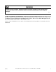
Table of Contents Replacement Parts .............................................................................. 5 Safety Information.............................................................................. Explanation of Safety Messages........................................................... Important Safety Instructions ............................................................... 7 7 7 Installation...........................................................................................
Operation Instructions for NetMaster Washers .................................... Step 1: Load Laundry....................................................................... Step 2: Close Loading Door............................................................. Step 3: Add Laundry Supplies ......................................................... Step 4: Set Fabric Selector ............................................................... Step 5: Set Wash Temperature...........................................
Replacement Parts If replacement parts are required, contact the source from which you purchased your washer, or contact: Alliance Laundry Systems Shepard Street P.O. Box 990 Ripon, WI 54971-0990 U.S.A. Phone: (920) 748-3950 for the name and address of the nearest authorized parts distributor.
Notes 6 © Copyright, Alliance Laundry Systems LLC – DO NOT COPY or TRANSMIT 801479
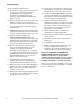
Safety Information Explanation of Safety Messages Important Safety Instructions Throughout this manual and on machine decals, you will find precautionary statements (“DANGER,” “WARNING,” and “CAUTION”) followed by specific instructions. These precautions are intended for the personal safety of the operator, user, servicer, and those maintaining the machine.
Safety Information 10. Do not tamper with the controls. 11. Do not repair or replace any part of the washer, or attempt any servicing unless specifically recommended in the user-maintenance instructions or in published user-repair instructions that you understand and have the skills to carry out. 12. To reduce the risk of an electric shock or fire, DO NOT use an extension cord or an adapter to connect the washer to the electrical power source. 13.
Installation Dimensions and Specifications 2 in. (5.1 cm) 29.6 in. (75.1 cm) 43.6 in. (110.7 cm) 31.1 in. (79 cm) 17.5 in. (44.8 cm) 14.3 in. (36.3 cm) 28 in. (71.1 cm) 26.9 in. (68.3 cm) 2 in. (5.1 cm) FLW1962N NON-GRAVITY DRAIN MODELS WITH OLD STYLE DOOR FLW1962N 2 in. (5.1 cm) 29.6 in. (75.1 cm) 43.6 in. (110.7 cm) 14.3 in. (36.3 cm) 31.1 in. (79 cm) 17.5 in. (44.8 cm) 28 in. (71.1 cm) 26.9 in. (68.
Installation 2 in. (5.1 cm) 29.6 in. (75.1 cm) 43.6 in. (110.7 cm) 31.1 in. (79 cm) 18.7 in. (47.5 cm) 14.3 in. (36.3 cm) 28 in. (71.1 cm) 26.9 in. (68.3 cm) 2 in. (5.1 cm) FLW2093N NON-GRAVITY DRAIN MODELS WITH NEW STYLE DOOR FLW2093N 2 in. (5.1 cm) 29.6 in. (75.1 cm) 43.6 in. (110.7 cm) 14.3 in. (36.3 cm) 31.1 in. (79 cm) 18.7 in. (47.5 cm) 28 in. (71.1 cm) 26.9 in. (68.
Installation Before You Start Electrical Tools Refer to serial plate for specific electrical requirements. For more detailed information, refer to section on Electrical Requirements. For most installations, the basic tools you will need are: 1 2 3 4 Water Washer needs two standard 3/4 inch (19.1 mm) water supply faucets with a pressure between 20 and 120 pounds per square inch (138 to 827 kPa). For more detailed information refer to section on Water Supply Requirements.
Installation Installing the Washer Step 2: Connect Fill Hoses NOTE: If the washer is delivered on a cold day (below freezing), or is stored in an unheated room or area during the cold months, do not attempt to operate it until the washer has had a chance to warm up. NOTE: Refer to section on Water Supply Requirements before connecting fill hoses. Step 1: Position Washer Near Installation Area Move washer so that it is within 4 feet (1.2 meters) of the desired area of installation.
Installation IMPORTANT: Hoses and other natural rubber parts deteriorate after extended use. Hoses may develop cracks, blisters or material wear from the temperature and constant high pressure they are subjected to. Step 3: (Non-Gravity Drain Models Only) Connect Drain Hose to Drain Receptacle All hoses should be checked on a yearly basis for any visible signs of deterioration. Any hose showing the signs of deterioration listed above should be replaced immediately.
Installation Standpipe Installation Step 4: (Gravity Drain Models Only) Connect Drain Outlet to Drain System Place the drain hose into the standpipe. Remove the beaded tie-down strap from accessories bag and place around standpipe and drain hose and tighten strap to hold hose to standpipe. This will prevent the drain hose from dislodging from drain receptacle during use. Remove drain fitting and hose clamp from accessories bag, and clamp fitting onto drain outlet.
Installation Step 5: Position and Level the Washer WARNING Washers elevated above floor level must be anchored to that elevated surface, base or platform. The material used to elevate the washer should also be anchored to the floor to ensure that the washer will not walk or that the washer can not be physically pulled, tipped or slid from its installed position. Failure to do so may result in conditions which can produce serious injury, death and/or property damage.
Installation Step 6: Remove the Shock Sleeves and Shipping Brace Remove front access panel by removing the two screws. Remove bolts and lockwashers from shipping brace with 9/16 in. wrench and remove brace. Remove shock sleeves by pulling on the yellow rope. Remove label from front side of front access panel and place on backside of front access panel.
Installation A junction box on the rear panel houses a terminal strip which furnishes supply output signals for the supply injection pumps. Refer to Figure 12 for the injection interface label. Supply Injection System Number of liquid supply connections (1–Detergent and 2–Softener) 2 Liquid supply connection size, in. (mm) 3/8 (9.52) or 1/4 (6.
Installation Step 9: Plug In the Washer Moving Washer to a New Location Refer to section on Electrical Requirements and plug the washer in. To prevent damage while moving the washer, the shipping materials MUST be reinstalled. Reinstallation of Shipping Materials Disconnect washer from electrical supply. Remove front access panel by removing two screws. Place the shock sleeves on all four shock absorbers. Refer to Figure 14.
Installation Electrical Requirements (120 Volt, 60 Hertz with 3-Prong Grounding Plug) NOTE: The wiring diagram is located in the control cabinet. The three-prong grounding plug on the power cord should be plugged directly into a polarized three-slot effectively grounded receptacle rated 110/120 Volts AC (alternating current) 15 Amps. Refer to Figure 16 to determine correct polarity of the wall receptacle. DO NOT OPERATE OTHER APPLIANCES ON THE SAME CIRCUIT.
Installation NOTE: Have a qualified electrician check the polarity of the wall receptacle. If a voltage reading is measured other than that illustrated, the qualified electrician should correct the problem. 2 1 3 0 V.A.C. 120 ± 12 V.A.C. 5 120 ± 12 V.A.C.
Installation Water Supply Requirements NOTE: Longer fill hoses are available (as optional equipment at extra cost) if the hoses supplied with the washer are not long enough for the installation. Order hoses as follows: WARNING Under certain conditions, hydrogen gas may be produced in a hot water system that has not been used for two weeks or more. HYDROGEN GAS IS EXPLOSIVE.
Installation Risers Risers (or air cushions) may have to be installed if the pipes knock or pound when flow of water stops. The risers are more efficient when installed as close as possible to the water supply faucets (refer to Figure 18).
Operation Operation Instructions for MDC Washers Step 2: Add Laundry Supplies IMPORTANT: Prior to first wash, use an allpurpose cleaner, or a detergent and water solution, and a damp cloth to remove shipping dust from inside of washtub. IMPORTANT: Remove all sharp objects from laundry to avoid tears and rips to items during normal machine operation. Open dispenser drawer. Measure and add low sudsing detergent (1), bleach (2) and fabric softener (3) to the dispenser drawer (refer to Figure 20).
Operation Step 3: Load Laundry Step 5: Insert Coin(s) or Card Load items loosely into wash drum. To Insert Money Check pricing as seen on digital display. OPERATING INSTRUCTIONS 1. Select Wash Temperature HOT, WARM, COLD. 2. Select Fabric Type NORMAL, PERM PRESS, DELICATE. 3. Load Supply Dispenser (See Instructions Below). 4. Load Clothes. 5. Insert Coin(s) / Card. 6. To Start Washer-Close Door and Push Start. DISPENSER INSTRUCTIONS 1. Open Dispenser Door. 2.
Operation Step 6: Start Washer DOOR LOCKED After vend price has been satisfied, push the START pad. DOOR MUST BE CLOSED TO START WASHER. DOOR LOCKED is lit whenever the door is locked. The door cannot be opened when this light is on. IMPORTANT: If washer fails to operate properly after installation, make sure electrical service and water supply faucets are turned on.
Operation Operation Instructions for NetMaster Washers Step 3: Add Laundry Supplies IMPORTANT: Prior to first wash, use an allpurpose cleaner, or a detergent and water solution, and a damp cloth to remove shipping dust from inside of washtub. IMPORTANT: Remove all sharp objects from laundry to avoid tears and rips to items during normal machine operation. Open dispenser drawer. Measure and add low sudsing detergent (1), bleach (2) and fabric softener (3) to the dispenser drawer (refer to Figure 28).
Operation Step 4: Set Fabric Selector Step 6: Insert Coin(s) or Card Push touchpad for NORMAL, PERM PRESS or DELICATES cycle. Light indicates selection. To Insert Money Check pricing as seen on digital display. NOTE: Changes can be made to Fabric Selector setting up until the first fill is complete. NORMAL PERM PRESS DELICATES HOT WARM COLD START W387I Figure 31 H205I H205I Figure 29 To Insert Card Insert card into opening. Do not remove the card until REMOVE CARD LED is lit.
Operation Step 7: Start Washer INSERT COIN/CARD After vend price has been satisfied, push the START pad. DOOR MUST BE CLOSED TO START WASHER. INSERT COIN/CARD is lit to prompt the user to insert coins or card to satisfy the vend price. When INSERT COIN/CARD is lit, the digits and decimal point show the vend price remaining to be satisfied.
Maintenance User-Maintenance Instructions Replacing Hoses Cold Weather Care Hoses and other natural rubber parts deteriorate after extended use. Hoses may develop cracks, blisters or material wear from the temperature and constant high pressure they are subjected to. If the washer is delivered on a cold day (below freezing), or is stored in an unheated room or area during the cold months, do not attempt to operate it until the washer has had a chance to warm up.
Maintenance Before You Call for Service You may save time and money by checking the following: If the Washer: Won’t Fill Won’t Start Won’t Tumble Won’t Spin Won’t Drain Be sure power cord is plugged all the way into the electrical outlet. • • • • • Close the loading door tightly. • • • • Check the laundry room fuse or circuit breaker. • Turn on the hot and cold water faucets. • Clean the screens in the water mixing valve and the filter screens in the fill hoses.
Maintenance If Service Is Required If service is required, contact the nearest Factory Authorized Service Center. If you are unable to locate an authorized service center or are unsatisfied with the service performed on your unit, contact: Alliance Laundry Systems Shepard Street P.O. Box 990 Ripon, WI 54971-0990 U.S.A. Phone: (920) 748-3121 When calling or writing about your unit, PLEASE GIVE THE MODEL AND SERIAL NUMBERS. The model and serial numbers are located on the nameplate.
Maintenance Information for Handy Reference Alliance Laundry Systems Shepard Street P.O. Box 990 Ripon, WI 54971-0990 U.S.A. Date Purchased Model Number Serial Number Dealer’s Name Dealer’s Address Phone Number Service Agency Service Agency Address Phone Number NOTE: Record the above information and keep your sales slip. Model and serial numbers are located on the nameplate.
Installer Checklist Fast Track for Installing the Washer (Refer to the manual for more detailed information) ➊ ➎ • Position Washer Near Installation Area. • Position and Level the Washer. FLW2095N FLW2095N CHECK ➋ CHECK H054IE0A H054IE0A • Connect Fill Hoses. ➏ COLD HOT • Remove the Shock Sleeves and Shipping Brace. H027IEOB TLW1976N TLW1976N CHECK CHECK ➌ ➐ (Non-Gravity Drain Models Only) • Connect Drain Hose to Drain Receptacle. • Wipe Out Inside of Wash Drum.