
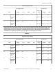
Specifications


Do not attempt to make chemical injection electrical connections
to points other than those provided specifically for that purpose
by the factory.
PHM940N_SVG
4
3
2
1
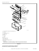
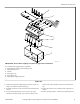
* Use a check valve on the end of tubing
† Must be mounted below the injection point
1. Injection Point*
2. Loops
3. Chemical Dispenser Pumb Outlet †
4. PVC Pipe
Figure 25
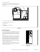
External Supplies
For proper communication between the machine and an external
chemical supply system, it is important for the low-voltage signal
power to be connected properly. The included wiring diagram
shows several different options for safe and correct wiring of this
interface.
The preferred method for connecting the wiring from the external
chemical supply system to the machine is to use the 300mA pow-
er of the machine’s 24VAC control transformer, which is inten-
ded strictly for this purpose. Other voltage and current options
are available, but require some wiring changes and must be pro-
vided with an external power source. Under no circumstances
should the high-voltage machine supply connections or source be
used for the communication wiring.
Communication wiring connections, which include a single row
of identified terminal blocks, can be found under a service panel
at the upper back of the machine.
NOT 00mA
whi
Internal
Supply
JUMPER FOR INTERNAL
24 VAC SUPPLY
CONNECTED TO RELAY
T IF NOT
WIRING TO INTERNAL
24 VAC SUPPLY
24 VAC
24 VAC
ES 1
EXAMPLE FOR EXTERNAL
DISPENSER CONNECTION
EXTERNAL DISPENSER CONNECTIONS
RELAY COM
SUPPLY 1
24 VAC
External
Dispensing
System
24 VAC COM
ES 2
ES 3
ES 4
ES 5
ES 6
ES 7
ES 8
RELAY
COM
RED
PHM842N_SVG
Figure 26
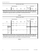
Specifications and Dimensions
58
©
Copyright, Alliance Laundry Systems LLC - DO NOT COPY or TRANSMIT F8423301ENR3