
Specifications


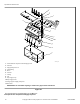


Connecting External Liquid Supplies
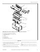
1. Remove knockout from supply dispenser. Refer to Figure 23 .
Plugs are assembled inside the tubing ring.
2. Install strain relief connector in hole with strain reliefs, inclu-
ded in the seal nut.
3. Insert tubes through base. Do not remove cups. Tube should
extend into the plastic cup, with the exception of the softener
tube, which should be routed to the outside of the cup.
4. Tighten the seal nut to prevent tubing from escaping the as-
sembly.
5. Before operating machine, confirm lid is completely closed.
Do not attempt to make chemical injection electrical connections
to points other than those provided specifically for that purpose
by the factory.
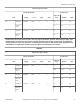
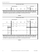
Chemical Injection Supply System
Number of dry supply com-
partments
5
Chemical Injection Supply System
Number of external liquid
supply connections
8
Liquid supply connection
size, in. [mm]
0.625 [15.9 ]
Table 30
Specifications and Dimensions
F8423301ENR3
©
Copyright, Alliance Laundry Systems LLC - DO NOT COPY or TRANSMIT 55