
Specifications


PHM829N_SVG
8
7
6
5
4
3
2
1
A
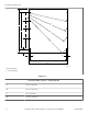
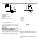
Direct Drain System
1. Drain Pipe
2. Overflow Pipe (optional)
3. Vent
4. Trap (if required by local codes)
5. Steel Grate
6. Drain Trough
7. Strainer
8. Waste Line
9. 3 in. [76 mm] minimum gap
Figure 15
All drain systems must be vented to prevent an air lock and to
prevent siphoning.
Refer to Figure 15 .
IMPORTANT: Machines must be installed in accord-
ance with all local codes and ordinances.
If proper drain size is not available or practical, a surge tank is
required. A surge tank along with a sump pump should be used
when gravity drainage is not possible.
Increasing the drain hose length, installing elbows, or causing
bends will decrease drain flow rate and increase drain times, im-
pairing machine performance.
PHM830N_SVG
8
9
7
6
5
4
3
2
1
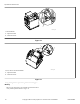
Drain Trough System
1. Rear of Machine
2. Drain Pipe
3. Overflow Pipe (optional)
4. Steel Grate
5. Drain Trough
6. Strainer
7. Waste Line
8. 1 in. [25 mm] minimum gap
9. 3 in. [76 mm] minimum gap
Figure 16
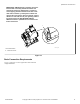
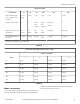
Refer to Table 13 for capacity-specific drain information.
NOTE: Installation of additional machines will require
proportionately larger drain connections. Refer to Table
14 .
IMPORTANT: Do not block the machine overflow open-
ing.
If water or suds flow from the machine overflow vent and the
machine has been verified to be operating properly with proper
water levels and correct amount of laundry chemicals, a drain
line may be added to the machine overflow vent and routed to a
drain trough.
1. Route a drain pipe from the machine overflow to a drain
trough. Drain pipe should be routed straight across or down
and be suspended above drain trough by at least 3 inches [76
mm].
IMPORTANT: Do not route the machine overflow to a
direct drain system.
Specifications and Dimensions
38
©
Copyright, Alliance Laundry Systems LLC - DO NOT COPY or TRANSMIT F8423301ENR3