
Specifications
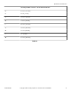


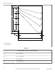

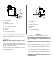
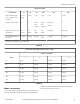


Mounting Bolt Hole Locations – 150 Pound Models
E 47.88 in. [1216 mm]
F 57.4 in. [1457 mm]
G 12.13 in. [308 mm]
H 15 in. [381 mm]
I 67.1 in. [1704 mm]
J 4 in. [102 mm]
K 1.5 in. [38.1 mm]
L 47 in. [1193 mm]
M 50 in. [1270 mm]
Table 12
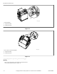
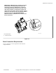
Gap Setting for Vibration Switch
After the machine has been properly installed, the vibration
switch gap must be verified. To locate the vibration switch refer
to Figure 12 , Figure 13 and Figure 14 . For UniLinc models,
while the control is displaying the Inputs Outputs Menu the alarm
will sound when the frame switch is activated. To verify and set
the vibration switch gap use the following procedures:
WARNING
Only trained personnel should perform this proce-
dure. Use caution while servicing machines with
covers removed and power applied.
W700
For UniLinc Models, Navigate to the Inputs Outputs
Menu:
1.
From the Cycle Menu press and hold the
, ,
keys to enter the System Menu.
2. Press the arrow keys to highlight the Diagnostic box.
3.
Press the key to enter the Diagnostic Menu.
4.
Press the key to enter the Test Menu.
5. Press the arrow keys to highlight the Inputs Outputs box.
6.
Press the
key to enter the Inputs Outputs Menu.
Verify Vibration Switch Gap [35-125 Pound Models]:
1. Insert 0.009 inch feeler gauge between the adjustment bolt
and the vibration switch; the alarm must not activate.
2. Remove the feeler gauge.
3. Insert 0.010 inch feeler gauge [supplied with machine] be-
tween the adjustment bolt and the vibration switch; the alarm
must activate.
4. Remove the feeler gauge.
5. Adjust the vibration switch adjustment bolt if necessary. Re-
fer toFigure 12 and Figure 13 .
Specifications and Dimensions
F8423301ENR3
©
Copyright, Alliance Laundry Systems LLC - DO NOT COPY or TRANSMIT 35