
Specifications


the threaded end of the bolts should extend 3 inches [76 mm]
above the mounting surface.
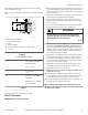
Refer to Figure 5 for a typical installation of individual mounting
bolts.
PHM862N_SVG
D
C
B
A
5
4
3
2
1
E
Acrylic Adhesive Anchors
1. Machine Frame Base
2. Grout
3. Acrylic Adhesive
4. Anchor Bolt [minimum Grade 5 SAE rating]
5. Concrete
Figure 5
Acrylic Adhesive Anchors
A 2 in. [64 mm] [minimum
thread extension]
B 3/4 in. [19 mm]
C 6 in. [165 mm]
D 4 in. [102 mm] [minimum
embedment]
E Drill hole size per manufac-
turer requirements
Table 5
Machine Mounting and Grouting
After the concrete has cured, proceed as follows:
1. Place the machine adjacent to the foundation. Do not attempt
to move the machine by pushing on the sides. Always insert a
pry bar or other device under the bottom frame of the machine
to move it into place.
2. Remove the wood skid by unscrewing the carriage bolts hold-
ing the skid to the bottom frame of the machine.
3. Place the machine carefully over the anchor bolts. Never at-
tempt to lift the machine by the door handle or by pushing on
the cover panels.
4. Raise and level the machine 0.5 inch [12.7 mm] off the floor
on four points, using spacers such as nut fasteners.
WARNING
Crush hazard. To avoid personal injury and/or
property damage, do not tip the machine more
than 25 degrees in any direction.
W793
5. Fill the space between the machine base and the floor with a
good quality non-shrinking machinery precision grout to
ensure a stable installation. Grout completely under all frame
members [remove front panel and back panel to gain access to
all frame members]. Refer to Table 6 . Force grout under ma-
chine base until all voids are filled.
6. Before grout sets completely, make a drain opening in the rear
of the machine grouting with a stiff piece of wire; this open-
ing should be approximately 0.5 inch [12.7 mm] wide to al-
low any surface water build-up under the base of the machine
to drain away. Do not omit this step.
7. Position the mounting bolt lockwashers and locknuts on the
anchor bolts and finger-tighten locknuts to machine base.
8. Allow machine grout to set, but not cure.
9. Remove the spacers carefully, allowing the machine to set-
tle into the wet grout.
10. After the grout is completely cured, tighten the locknuts by
even increments – one after the other – until all are tightened
evenly and the machine is fastened securely to the floor.
11. Torque 5/8 inch bolts [35 model] to 90 ft.-lbs. and torque 3/4
inch bolts [60-150 models] to 160 ft.-lbs.
NOTE: Check and retighten the locknuts after five to
ten days of operation and every month thereafter. Refer
to Maintenance section.
Grout Placement
IMPORTANT: Grouting is required.
Specifications and Dimensions
F8423301ENR3
©
Copyright, Alliance Laundry Systems LLC - DO NOT COPY or TRANSMIT 21